


Hardware components | ||||||
 |
| × | 1 | |||
 |
| × | 1 | |||
 |
| × | 1 | |||
| × | 1 | ||||
 |
| × | 1 | |||
Software apps and online services | ||||||
 |
| |||||
What Are Snap Circuits?
Snap Circuits makes learning electronics easy and fun! Learn how to integrate Snap Circuits with your hardware. Fun for Kids!
Introductory Project
If you have not completed the introductory project, please see Snap Circuits - Introduction. This project also contains a complete index of Snap Circuit projects.
Let's Get StartedProject Objective
This experiment will demonstrate how to control two LEDs using a single output pin on the Snapduino.
Building the Circuit
The minimum set requirement for this project is SC-300 and the Snapduino. Build the following circuit by following the directions in the PDF file:
Scroll down to see and download the PDF file containing complete build instructions (the PDF file can also be found in the GitHub repository).
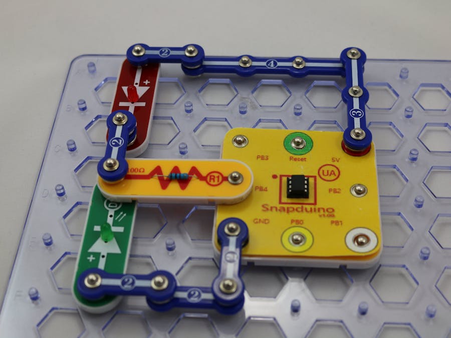
Completed CircuitThe Circuit
The two LEDs in the circuit are connected in an "opposite" manner. What that means is the anode of one LED is connected to the Snapduino pin while the cathode of the other LED is connected to the same pin. When the Snapduino output pin is HIGH, the LED with the anode connected allows the current to flow to GND and thus will be on while the other LED is blocking the current and is off. When the Snapduino output pin is LOW, the LED with the cathode connected allows current to flow to 5V and thus is on while the other LED blocks the current and is off.
The Software
The sketch will set the pin to OUTPUT mode and toggle the value between HIGH, LOW and floating. Note when the pin is floating, neither LED is on because no current flows from the pin. Note, to get the pin in floating state, the mode of the pin is changed to INPUT.


Comments
Please log in or sign up to comment.