


Hardware components | ||||||
 |
| × | 1 | |||
 |
| × | 1 | |||
 |
| × | 1 | |||
| × | 1 | ||||
 |
| × | 1 | |||
Software apps and online services | ||||||
 |
| |||||
Follow the Snap Circuits platform!
OverviewWhat Are Snap Circuits?
Snap Circuits makes learning electronics easy and fun! Learn how to integrate Snap Circuits with your hardware. Fun for Kids!
Introductory Project
If you have not completed the introductory project, please see Snap Circuits - Introduction. This project also contains a complete index of Snap Circuit projects.
Let's Get StartedProject Objective
This experiment will demonstrate how the Snapduino can control an analog motor using an SCR.
Building the Circuit
The minimum set requirement for this project is SC-500 and the Snapduino. Build the following circuit by following the directions in the PDF file:
Scroll down to see and download the PDF file containing complete build instructions (the PDF file can also be found in the GitHub repository).
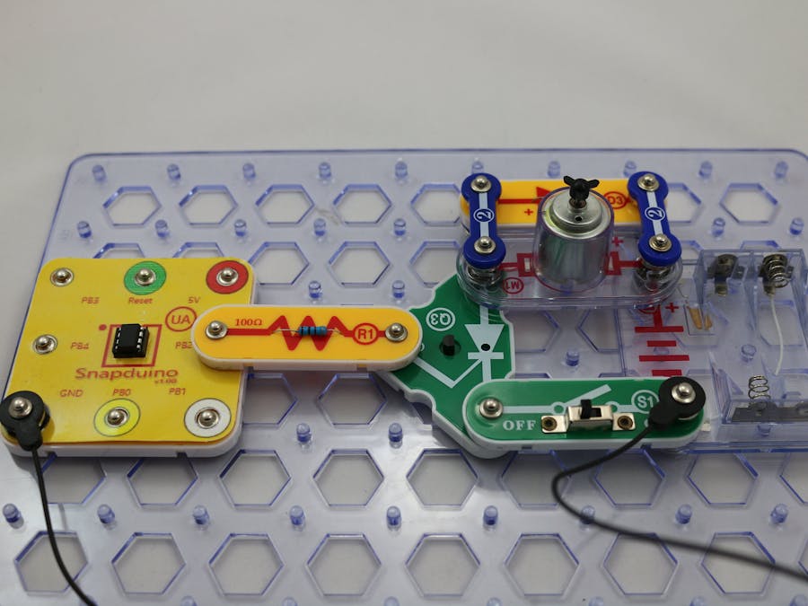
Completed CircuitThe Circuit
The SCR (Silicon Controlled Rectifier) is a rectifier diode with a third pin called the gate. This pin controls the current flow in the forward direction through the diode. When a small current applied to the gate current will flow through from the anode pin to the cathode pin.
The diode D1 is there to block the motor back current to keep it from flowing back into our circuit. When the motor runs, it builds up an internal current that is released when the motor stops. This current (with a voltage spike) can damage the transistor or the Snapduino.
The Software
The sketch in this example sets the Snapduino pin to output mode and then toggles the pin between HIGH and LOW for three seconds each. This results in the motor running for three seconds and then turning off for three seconds, repeating this pattern indefinitely.


Comments
Please log in or sign up to comment.