Follow the Snap Circuits platform!
OverviewWhat Are Snap Circuits?
Snap Circuits makes learning electronics easy and fun! Learn how to integrate Snap Circuits with your hardware. Fun for Kids!
Introductory Project
If you have not completed the introductory project, please see Snap Circuits - Introduction. This project also contains a complete index of Snap Circuit projects.
Let's Get StartedProject Objective
This experiment will demonstrate connecting the Snapino to a IFTTT Maker Webhook using the Arduino WiFi 101 Shield and the Snap Circuits Motion Detector to trigger events.
Building the Circuit
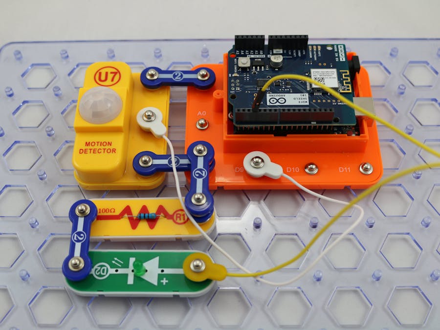
The minimum set requirement for this project is SC-300, Snap Motion and the Snapino. Build the following circuit by following the directions in the PDF file:
Scroll down to see and download the PDF file containing complete build instructions (the PDF file can also be found in the GitHub repository).
Completed CircuitIFFFT is a web site that allows you to configure triggers and action events that can be tied to IoT devices as well as many other services such as Twitter and Facebook. It stands for "If this then that".
We will use it in this project to trigger an action from the motion detector. See the attachment at the end of the project that describes how to setup your account and create the triggers and actions for this project.
In the instructions document for setting up IFTTT, there are instructions on how to setup SMS in case you do not have a LIFX bulb or some other service to trigger an action on. Here is a screen shot of the SMS text messages sent from IFTTT.
The Circuit
The motion detector component U7 can detect motion when powered with 5V. The middle snap on the U7 component will have an output of HIGH when motion is detected and LOW when there is no motion. The Snapino monitors the output of the motion detector on pin 9.
The LED D1 is connected to pin 3 through the current limiting resistor R1 to ground. When pin 3 is HIGH, the LED will turn on. When pin 3 is LOW the LED will turn off.
The Software
The sketch will initialize pin 9 for INPUT and pin 3 for OUTPUT. It also initializes the Wi-Fi network. When motion is detected, the LED is turned on and a "motion" event is triggered on IFTTT. When pin 9 goes LOW (no motion), the LED is turned off and the "nomotion" event is sent to IFTTT.


Comments
Please log in or sign up to comment.