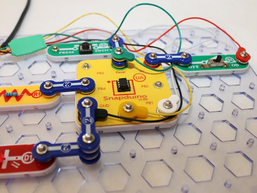
Snap Circuits make learning electronics easy and fun! The projects in the Snap Circuits platform are designed for younger kids who want to be introduced to IoT.
This project is a more advanced project demonstrating how to build an Arduino compatible that can be snapped onto the Snap Circuits grid. This project has some steps that may not be easy for a younger child to perform. An adult should guide the child or perform the steps for them.
Snap Circuits provides the SCM400 kit with microcontroller experiments utilizing the PICAXE-08M which provides the young learner with fun microcontroller experiments. The Snapduino attempts to provide a similar microcontroller experience, but instead, utilizing the vast resources found on the Arduino platform.
Minimum RequirementsThis project steps through the complete build of a product that is designed for a a child to use in experimenting on the Arduino paltform. Connections made to the microcontroller are made the snap wires in the same manner as any other Snap Circuit component. This project utilizes the Snap Circuits Eight-Pin IC Socket (U8).
The Snapduino includes a label that can be printed and place over the U8 socket that makes programming and connecting to the microcontroller easy.
If you are interested in using only the ATtiny85 with Snap Circuits, some of the project steps can be skipped. If you are interested in building the complete product, jump to the section labeled "Updating the Arduino IDE".
Skipping the Label
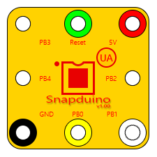
Creating and applying the label is optional, however, not having the label will make it harder to follow the experiments. The U8 has the pin numbers printed next to each snap. The guide below can be used to reference the pin numbers against the Snapduino labels.
Skipping the U8 Socket
Building the Snapduino requires the purchase of the U8 Eight-pin IC Socket from Snap Circuits. This allows the ATtiny85 chip to be placed into the socket and used directly in the experiments with the snap wires. If you are unable to purchase the socket, the circuit can be built on a breadboard and used with the snap-to-pin wires.
Skipping the Snap-FTDI Cable Build
The Snap-FTDI cable is used to upload sketches to the ATtiny85 directly while plugged into U8 socket, eliminating the need to remove the chip from the socket to place it into a programmer. If the U8 socket is not used, constructing this cable can also be skipped. Note, the cable is still required to program the chip after the bootloader is burned).
Skipping the Breadboard
The breadboard step has been added to allow for testing prior to assembling the Snapduino. Although this step is highly recommended, it is optional.
Updating the Arduino IDEThe ATtiny85 chip will be flashed and subsequently programmed using the Arduino IDE. To do this, the board needs to be installed into the IDE.
The first step in doing this is to add the board URL to the Additional Boards Manager URL list under Preferences. Select Preferences from the File menu and copy and paste the Snapduino URL (shown below) into the text box. If there are already other URLs in the box, just add a comma at the end before pasting it.
https://raw.githubusercontent.com/porrey/Snapduino/IDE/package_porrey_snapduino_index.json
You can also select the button to the right of the text box to open a second window that will display the URLs in a list. Paste the URL as the last item in the list and then close all of the windows.
Next, go to the Tools menu and select Board. In the popup menu, choose Boards Manager. In the search text box, type Snap to filter the list so that it only shows the Snapduino board. Next, click the Install button to add the board. Finally, click the Close button.
This completes the installation. There is now a board called Snapduino in your boards menu. Select this board whenever you are working with the Snapduino.
The images below correspond to the steps given above.
The ATtiny85 chip normally requires a programmer to load sketches. This would require the chip to be pulled out of the U8 socket and placed into a programmer each time. To avoid this complexity, we will put a bootloader onto the chip that will allow sketches to be downloaded using an FTDI cable allow the chip to remain in the U8 socket.
Loading the bootloader to the chip only has to be done once. Performing this step does require access to a programmer. The best programmer for the ATtiny85 (in my opinion) is the Tiny AVR Programmer from SparkFun. If you do not want to invest the money in one of these, it is possible to use another Arduino, such as the Uno, to program the chip. Here are a couple of very useful resources that show how to do this.
- Programming ATtiny85 with Arduino Uno on Hackster.io
If you have a programmer, place the ATtiny85 into the programmer and connect it to the USB port on your computer. Open the Arduino IDE and select the Snapduino board from the Tools menu. In the Programmer menu under Tools, select the correct programmer. If you have the SparkFun AVR Tiny Programmer, choose USBtinyISP. Now click Burn Bootloader from the tools menu.
Pay close attention to the messages in the IDE when the process is underway. It is rare that it will fail but it may happen. If the Arduino IDE reports that the process has failed, simply repeat it.
Always make note of the clock speed that was selected when you burn the bootloader and ensure that all sketches are loaded with the same selection. If you do not use the same selection, your sketches will work but your timing will be off.
Choosing 8Mhz or 16MHzThe choice of clock speed can be made using one simple decision point: will you be supplying your circuit with 3.3V or 5V? If you are supplying your circuit with 5V, then choose 16MHz. If you are supplying your circuit with 3.3V, then 8MHz.
If you are unsure of the voltage, or know that the voltage will vary from experiment to experiment, I recommend using 8MHz. All of the Snap Circuit experiments that I post will work at 8MHz.
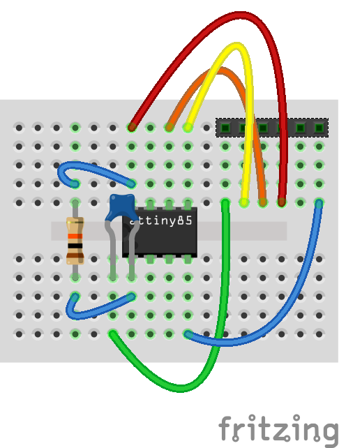
I always like to start on a breadboard to ensure everything is working properly, especially when soldering is involved. Although assembling this device is only a few small steps, it is important to have everything working before committing the design. The will save the need to unsolder components later.
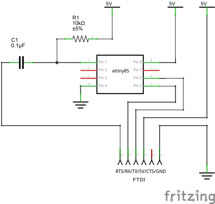
Using the schematic and breadboard diagrams attached to this project, assemble the circuit on the breadboard. The images below show a tiny breadboard but any size can be used.
Once assembled, connect the FTDI cable to the breadboard using a six-pin male-to-male header. If you do not have a header, you can insert six male-to-male jumper wires into the FTDI cable and connect the wires to your breadboard. Connect the USB cable to your computer.
Tune the BootloaderThe bootloader being used for the Snapduino requires a one-time tuning process to allow it to synchronize with the serial interface. This process ensures that the uploading process will be consistent.
NOTE: This step assumes you have built the circuit on a breadboard. If not, you will need to assemble the Snap-FTDI cable before performing the tuning.
Open the Arduino IDE and select the Serial Monitor from the Tools menu. When the window appears, set the baud rate from the drop down, located at the bottom right corner of the screen, to 9600 if you burned the bootloader at 8MHz, or choose 19200 if you used 16MHz.
A message will appear from the device asking you to send an 'x' slowly until the bootloader has completed the tuning process. Simply place and 'x' in text box at the top of the window and press send. Repeat this until the bootloader indicates it has completed. Once you have completed this step, you will not need to repeat it again unless you burn the bootloader again.
The overlay label is designed to make connections to the Snapduino easier. The pins are clearly labeled for both circuit and programming connections. The FTDI cable connections are color coded which make it simple to connect the cable to upload a sketch.
The label is attached as several files to provide a few options for printing. If you have Adobe Photoshop or Photoshop Elements, this format offers the best approach when printing. If you do not have either version of Photoshop, try the PDF or PNG files.
For best results, print on a sheet of high quality photo paper. The overlay image will fit on either a 5" x 7" full sheet, or an 8" x 10" full sheet. I recommend printing two copies on the same page (to have a backup). This can be done by printing the first copy and then turning the sheet around in the printer and printing the second copy.
Now that you have it printed, the template needs to be cut. I used an X-Acto knife on a cutting board to carefully trim the edges and cut out the holes and the center square.
Start by cutting the outer square using a straight edge along all four sides. Next, carefully trim the rounded corners. Now remove all eight of the smaller white circles being sure to leave the outer color circles intact. Finally, cut the entire red square out from the center.
My wife has scrapbooking tools so I was able to use her rounded corner cutter on the corners. I also found that a standard whole punch, normally used to put paper in a binder, is almost the perfect size for these holes. I did cut several of these only using the knife, and was able to do that successfully, but if you have either of the tools I mentioned, it is much easier! The image below shows the final cut as well as the tools used.
There are four components that need to be added to the U8 socket to make it a Snapduino. They are the overlay label, the ATtiny85, a 10K Ω resistor and a .1 µF ceramic capacitor.
The first step is to separate the top plate of the U8 IC Socket from the bottom white plate. To do this, take a small precision flat head screwdriver and carefully press them into the eight slots, one at a time, found on the top side near the edge (where the yellow plate and the white plate come together). Slide the screwdriver straight down into the small slot and then pry it open slightly. Repeat this all the way around the part until the top portion has been completely separated. Folow the steps below to build the componenet.
- Remove the wire from pin 1 using a soldering iron. Carefully heat the solder at the tab and pull the wire off using a pair of needle-nose pliers. The wire may just pop off when it is heated.
- Solder one end of the .1 µF capacitor to the tab on pin 1.
- Solder one end of the 10K Ω resistor to the tab on pin 8 being careful not to detach the existing wire.
- Solder the end of the wire that was detached from pin 1 together with the other end of the resistor and the capacitor so that all three are connected together.
- Carefully push the new components down so that they are flat against the bottom of the plate.
- Reconnect the bottom and top plates.
- Push the ATtiny85 into the socket on the top side of the plate ensuring that the dot on the chip aligns with the red dot on the plate.
- Place the overlay template onto the socket. The center cut-out is sized so that the label will hold in place without the need for glue. If you like, you can rub a small amount of glue (some type of tacky glue) on the underside of the overlay and then press it down. You can also try a repositionable adhesive to make it easier to palce the overlay.
To keep with the theme of Snap Circuits, the ends of FTDI cable needs to snap onto the Snapduino pins. This is fairly straightforward to do using a Snap-to-Pin wire set for Snap Circuits.
For this step, we will use one each of the red, black, green, yellow and white snap-to-pin wires.
- To make it easier to connect, snap the five wires together in this order: black, red, white, yellow and green.
- Push the pin end of the black wire into the FTDI connector so that it is connected to the black wire on the cable.
- Push the pin end of the red wire into the FTDI connector so that it is connected to the red wire on the cable.
- Push the pin end of the white wire into the FTDI connector so that it is connected to the orange wire on the cable.
- Push the pin end of the yellow wire into the FTDI connector so that it is connected to the yellow wire on the cable.
- Push the pin end of the green wire into the FTDI connector so that it is connected to the green wire on the cable.
- Cut a piece of electrical tape 4 cm in length and wrap it around the wires to keep them connected to the FTDI cable. Make sure the tape overlaps both the snap-to-pin wires and the FTDI connector.
- OPTIONAL: To make this kid-proof, cut a 3 cm piece of 1/2" (13 mm) shrink tube and place it over the connector. You will need to pass each snap wire through it one at a time to get all of the wires through. Using a shrink tube torch (or heat gun) shrink the piece snuggly over the connector being careful not to burn the wires.
The FTDI cable requires drivers to be loaded. Always refer to the manufacturer of your cable or the vendor you purchased the cable from to get and install the drivers. You will only need to perform the driver installation once.
Finding the COM Port NumberIn Windows, you can use the device manager to find the COM port number for your cable, however, you can also use the Arduino IDE to do this. The Arduino IDE will display all of the COM ports in the Port menu. Simply remove any other cable and your FTDI cable will be the only one listed (assuming you do not have any other COM devices attached to your computer).
Loading a SketchLoading a sketch works in the same manner as any other Arduino board.
This process always starts with connecting the snap ends of the Snap-FTDI cable to the Snapduino.
Ensure that the USB plug is disconnected from your computer when making connections. It is very easy to accidentally touch the wires together while manipulating the cable which could result in shorting out your USB port. I have done this a few times. Luckily, the damage was not permanent. Most USB ports have protection that disables power when too much current is drawn from the port. A reboot of the computer will get the port back online. Be aware that some USB ports may not have this protection, which will result in permanent damage. Using an external USB hub is a good idea if you are not sure. The hub will protect the ports on your computer in the case of an accidental short.
When connecting the cable, simply match the snap color to the color ring on the Snapduino. If you did not print the overlay, you will need to refer to the chart at the beginning of this article to make your connections.
In the Arduino IDE, assuming your sketch is coded and ready to upload, select the Snapduino board from the Tools menu and choose the correct clock speed (choose the same speed you used when you burned the bootloader). Ensure that the correct COM port is selected in the Port menu under Tools. Finally, select Upload from the Sketch menu.
Take a look at the Snap Circuits platform page to begin using your new Snapduino!
If you are interested in obtaining an ATtiny85 with the bootloader pre-loaded or a pre-printed overlay for the U8 socket please send me a private message through Hackster. I will attempt to work out payment and shipping. You will only need to pay for the parts plus shipping (I have no interest in making a profit).


Comments
Please log in or sign up to comment.