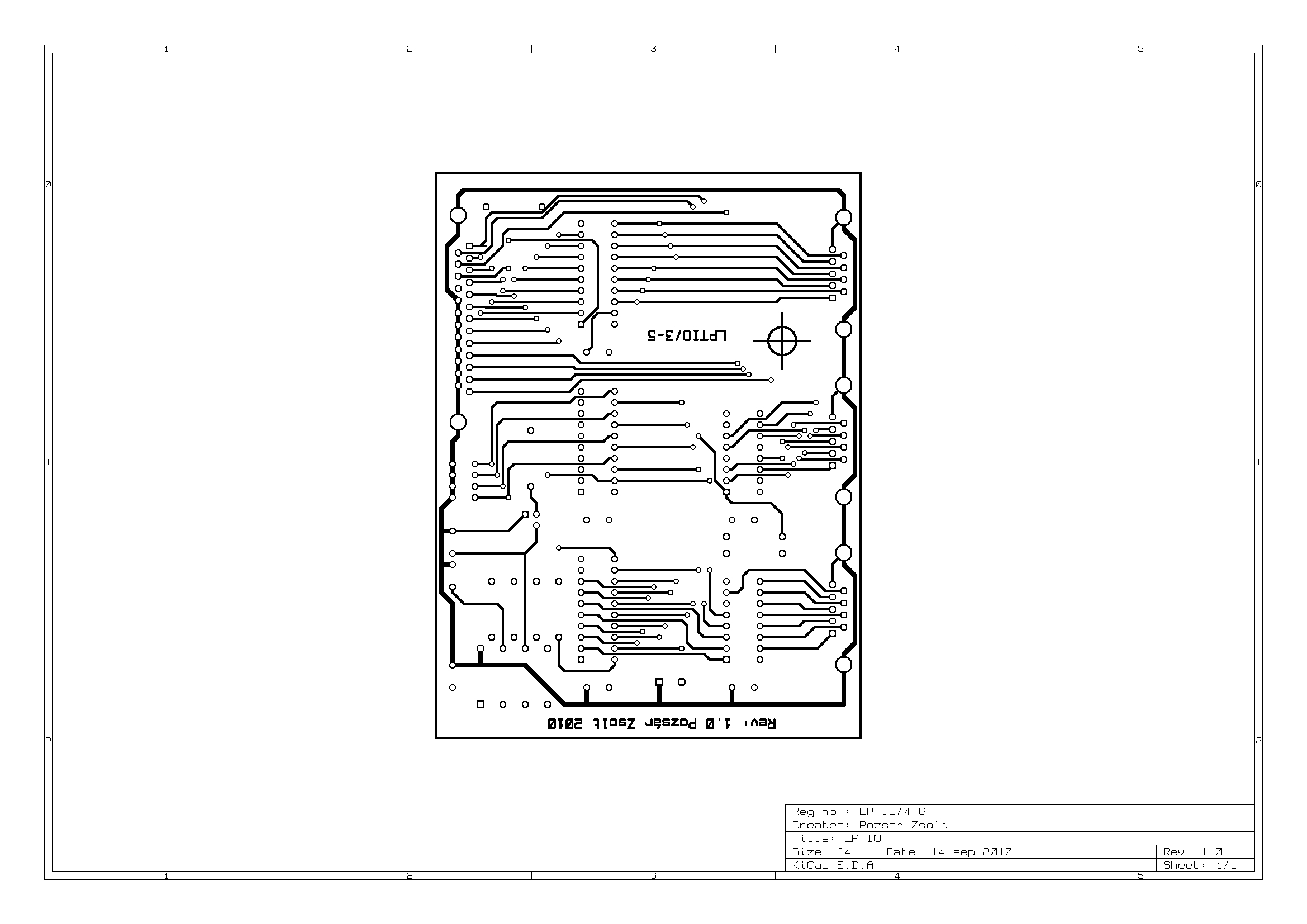
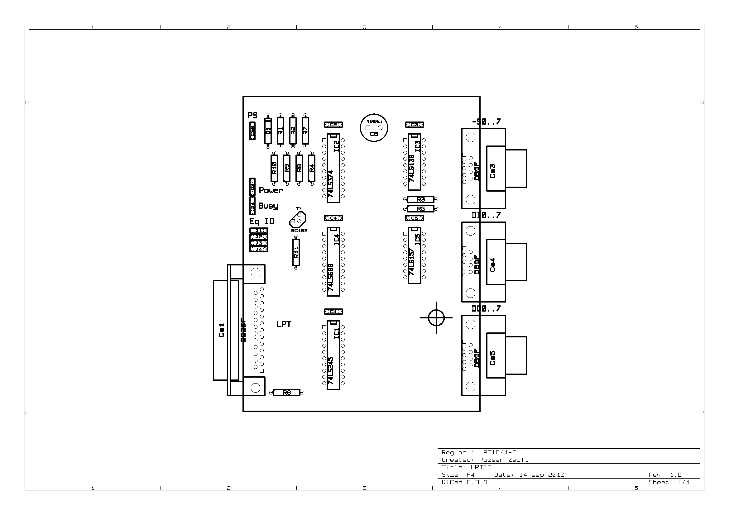
This device was made for testing the circuit boards of a later project. Unfortunately, despite 91% software and 78% hardware readiness, that project was stopped (because of work abroad) and has been waiting for its fate in a box ever since.)
CircuitInterface has eight settable equipment ID (EqID), eight select outputs, eight inputs and eight outputs and is connected to a computer via an LPT port.
The four-bit EqID identifies the device, which can be set using the front panel switch.
Before the I/O operation, the computer sends a 3-bit selector address and a 4-bit EqID, which is stored in an octal D type flip-flop circuit (74LS374). (Receives enable from -INIT line). The stored and set ID are compared by the comparator (74LS688), and if there is a match, the multiplexer circuit (74LS138) is enabled. The second enable comes on the LPT port on the -STROBE line. The match of the identifier is indicated to the computer on the -ERROR line. If the multiplexer is enabled, the selector line corresponding to the stored address is activated. The I/O operation from the selected address can then be performed
PC reads eight bits in two parts using the 4x2 input multiplexer circuit (74LS157). The half-byte data is entered on the BUSY, -ACK, SLCT and PE lines, -AUTOFD is used to select the lower and upper half-byte.
The output is buffered with a bus transceiver (74LS245) circuit to protect the same circuit of the LPT adapter. The PC writes 1 byte data through lines D0-7.
The device works with a voltage of 5V DC (220 mA). Power input is protected against wrong polarity.
You can find the schematic drawing in attached Github repository in KiCAD and Postscript format.
Printed circuit boardYou can find the drawings of PCB in attached Github repository in old KiCAD and Postscript format.
The housing of the device is made from the housing of an old and wrong external modem (BEST 1414 EC).
AccessoriesThe device comes with three measuring leads.
Pinout of thecable and wires
Cable between interface and PC (DB25M-DB25M):
- 1 -> 1... 16 -> 16: data lines
- 18-25 - > 18-25: GND
Selector lines (DB9M):
- 1: -S0
- 2: -S2
- 3: -S4
- 4: -S6
- 5: GND
- 6: -S1
- 7: -S3
- 8: -S5
- 9: -S7
Input and output lines (DB9M):
- 1: I0 / O0
- 2: I2 / O2
- 3: I4 / O4
- 4: I6 / O6
- 5: GND
- 6: I1 / O1
- 7: I3 / O3
- 8: I5 / O5
- 9: I7 / O7
The management program is a very simple command-driven program with a character interface. This is only for manual testing of the attached unit.
You can download binary for DOS and source code (with DOS and Linux version of pascal unit) from attached Github repository and from my hobby homepage.


Comments
Please log in or sign up to comment.