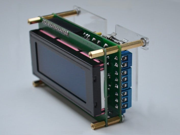
It is a simple serial console that can be used for data display and data input. It can handle three (different) serial interfaces at the same time: 3.3V TTL for single-board computers and microcontrollers, via traditional RS-232 and serial over USB.
I. Hardware1. Technical data- Supply voltage: 5 V DC
- Supply current: approx. 30 mA
- Mechanical size: 100 x 60 x 50 mm
- Insulation class: Class 0
- IP protection: IP 00
- Mass of cover: termoplastic (PC), only top cover
- Display size: 20x4 characters
- Displayed character set: ASCII 32-127
- Connection: 3.3V TTL, RS-232 and via USB serial ports
- Serial port receive buffer size: 255 byte
This is a Raspberry Pi Pico-based device. The display is 20x4 character-sized liquid crystal display, which displays 20x4 size area of the larger size virtual screen. This area is a can be moved with buttons. The default size of the virtual screen is 80x25 characters, this value can be set in the program.
The circuit has three serial ports, depending on the setting, all three can be used for data and system message transmission, or both at the same time. The #0 serial port is via USB port, #1 is a 3.3V TTL port, #2 is a conventional RS-232 serial port. Serial #1 can be connected to a 5V TTL serial port with an external level shifter circuit.
Default port speeds: 115200, 9600 and 9600 bit/s, these values can be set in the program.
The console has four operation modes, the first three for display only can be used, these are pre-programmed, the fourth is reserved for unique solutions. With jumpers between modes we can choose.
All connections are screw terminal blocks.
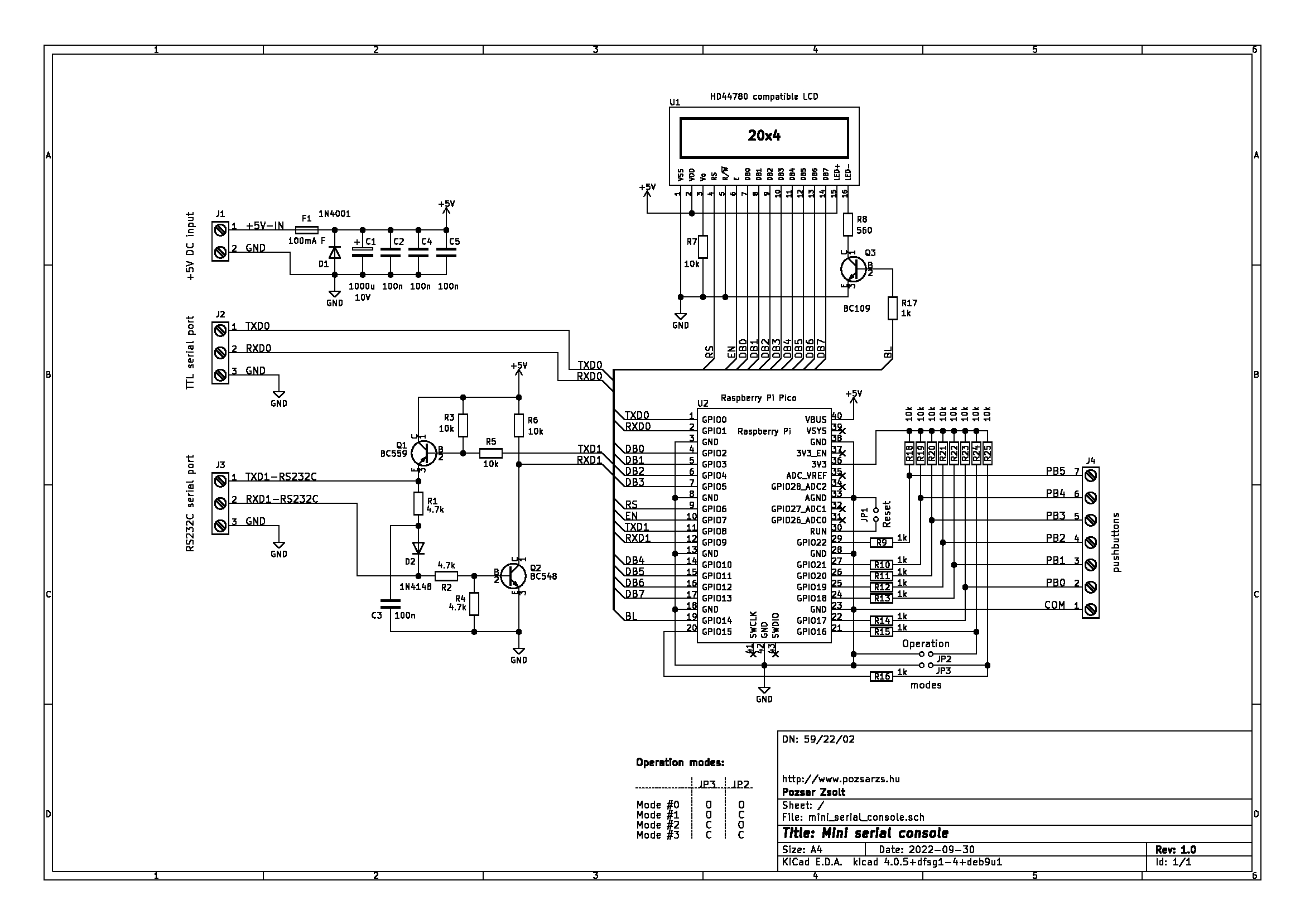
The supply voltage goes to the buffer and filter capacitors and other circuits through the fast-acting fuse F1. The function of the antiparallel diode is protection against reverse polarity supply voltage. If the USB port is in use, the device receives power from it, in which case the power input can only be used as a (low-load) output.
All peripherals are connected to the microcontroller. The signal from serial port #1 goes directly to the GPIO port through the level adapter of port #2. The push buttons and mode selection jumpers (JP2-3) are connected to the port through a protective resistor, in the open state a pull-up resistor ensures a stable high level.
The Hitachi HD44780 compatible display works in eight-bit write-only mode, the data and control lines directly connected to the GPIO ports. The program can turn the display backlight on and off. The contrast of the display depends on the resistor R7, its value may depend on the type of LCD module.
The device is operated by the program, so its detailed operation can be found in the Software section.
4. Manuals and connectors- 1: Fuse F1 - power supply
- 2: J1 connector - power input
- 3: J2 connector - TTL serial port
- 4: J3 connector - RS-232 serial port
- 5: J4 connector - push buttons
- 6: JP1 jumper - RESET
- 7: JP2-3 jumpers - mode selector
- 8: USB connector
You can download wiring diagrams as part of the complete documentation or in separate PDF, SVG and KiCAD formats from the developer/manufacturer's website. The Gerber files needed for production are included in the package.
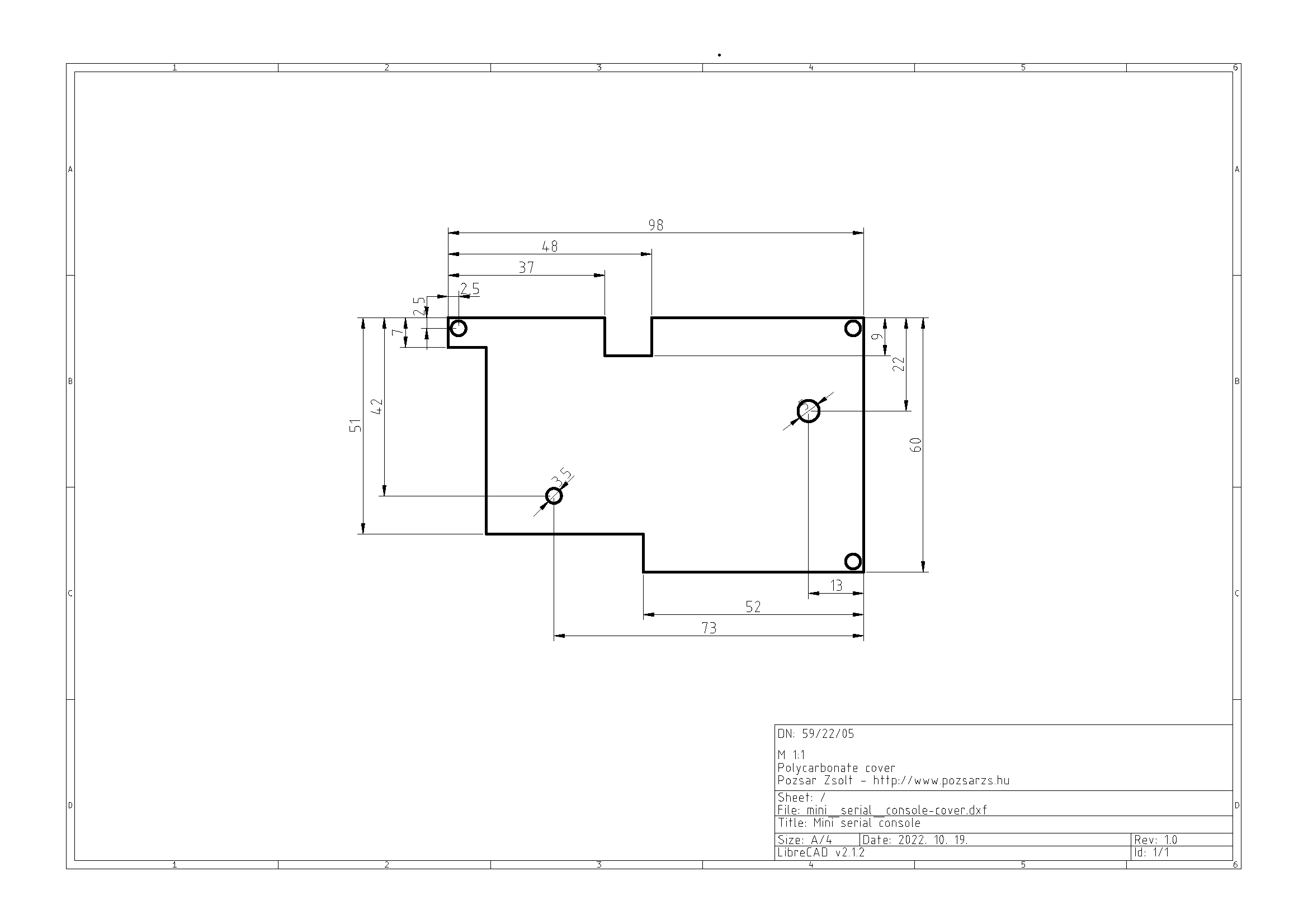
6. Other drawingYou can download mechanical drawing of polycarbonate cover as part of the complete documentation or in separate PDF, SVG and LibreCAD formats from the developer/manufacturer's website.
7. Terms of useHardware documentation can be modified and/or redistributed under the Creativ Commons 4.0 Attribution Non-Commercial (CC-BY-NC-4.0) License.
8. Downloadable documentationThe complete documentation of the hardware in the.tar.gz format compressed file can be downloaded from the manufacturer's website or Github.
II. Software1. General descriptionThe program that operates this device was created on the Arduino IDE development system. This application must first be prepared to work with the Raspberry Pi Pico, for which instructions can be found online (for example here).
2. SetupBefore installing the program, you need to set these prepocessor macros:
// enable 8 bit mode of the LCD
#define LCD_8BIT
// enable Serial #0 port
#define COM_USB
// enable Serial #1 port
#define COM_TTL
// enable Serial #2 port
#define COM_RS232C
// enable console messages on Serial #0 port
// #define COM_USB_MESSAGES
// enable console messages on Serial #1 port
// #define COM_TTL_MESSAGES
// enable console messages on Serial #2 port
// #define COM_RS232C_MESSAGES
and constants:
// settings
// LCD backlight off time after last button press
const int     lcd_bloffinterval = 60000;
// horizontal size of display
const byte    lcd_xsize         = 20;
//vertical size of display
const byte    lcd_ysize         = 4;
// horizontal size of virtual screen
const byte    virtscreenxsize   = 80;
// vertical size of virtual screen
const byte    virtscreenysize   = 25;
// speed of the USB serial port
const int com_speed[3] = {115200, 9600, 9600};At start-up, the program initializes serial ports and if consol messages is enabled sends status message. After that, it sets the GPIO ports, clears the virtual screen and initializes the display. Sets its own operating mode according to the jumpers (JP2-3). The display shows brief information about the device.
The program then continuously monitors all serial ports, the state of the buttons, and the state of the mode selection jumpers. If data is received on one of the ports, it is copied to the virtual screen. The LCD display shows a part of the virtual screen as a window. This 'window' can be moved with the buttons. The size of the virtual screen and the ability to move the 'window' depend on the selected mode.
The program turns off the backlight after 60 s of inactivity, then turns it back on when data is received or a button is pressed.
The program replaces the incoming TAB character (0x09) with SPACE (0x20), blinks the backlight in response to the BEL (0x07) character, and starts a new page to the FF (0x0B) in mode #2.
4. Terms of useThis program is free software: you can redistribute it and/or modify it under the terms of the European Union Public License 1.2 version.
This program is distributed in the hope that it will be useful, but WITHOUT ANY WARRANTY; without even the implied warranty of MERCHANTABILITY or FITNESS FOR A PARTICULAR PURPOSE.
5. Downloadable software packageThe package can be downloaded from the manufacturer's website or Github.
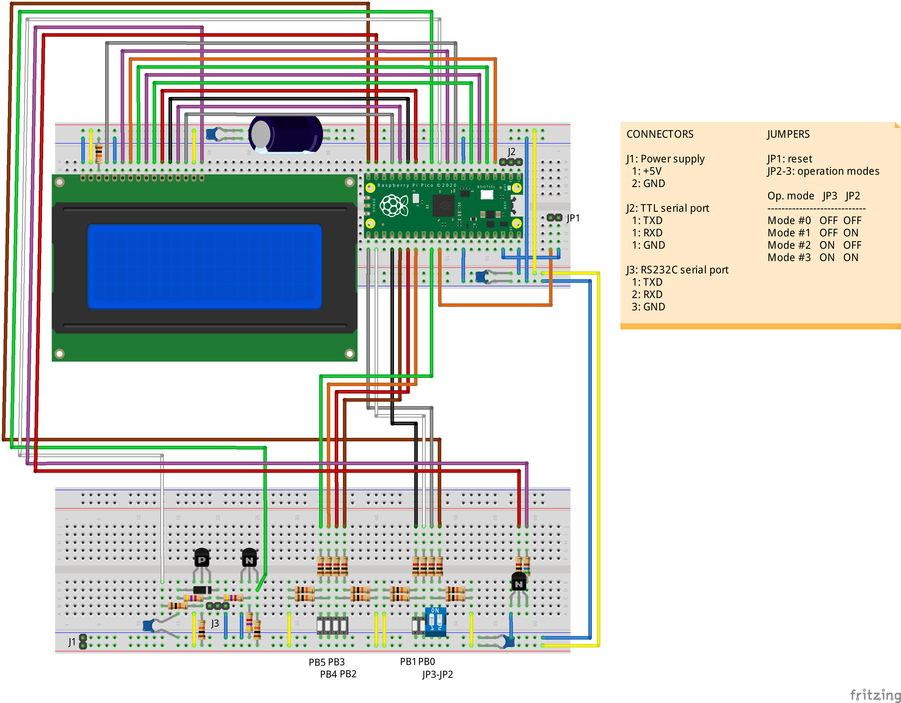
III. How to build this device1. On breadboardsThe wiring of the device is included in the attachment.
For the prototype, I also used a soldering test panel, on which the microswitches were placed.
The circuit received 5 V DC power during the test via the USB cable.
2. On printed circuit boardI made the panels again this time at PCBWay.
I did this activity using two computers. The Serial #0 and Serial #1 ports of the circuit were connected to the computer running Debian GNU/Linux, and the Serial #2 port was connected to the FreeDOS computer. Console messages is enabled in USB port.
The linux computer accessed the console of the circuit via /dev/ttyACM0, the first input via /dev/ttyUSB0, the DOS computer accessed the second input via COM1. (If the second input is also connected to the Linux machine, it will be available on /dev/ttySx.)
For testing, I used terminal programs, the Telix clone called Minicom on the linux machine, and the original Telix (from the early 90s) on the DOS machine. The port and communication parameters must be set on the terminal programs and it is advisable to turn on the local echo and line feed at the end of the line.
Example of starting minicom with command line parameters:
$ minicom --baudrate 115200 --device /dev/ttyACM0I alternately sent one line to the circuit with the terminal programs and checked correct displaying and scrolling. During the data transfer, the built-in green LED of the Pico lights up.
The system messages of the serial console can be viewed on the terminal program connected to the USB port.
It is advisable to test the device in operation modes #1...#3.


Comments
Please log in or sign up to comment.