


Good quality product and as described.
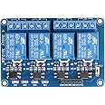
| Connector Type | Through Hole |
|---|---|
| Contact Material | Silver, Copper, Or Alloy |
| Contact Type | Form C Or Spdt |
| Current Rating | 10 Amps |
| Mounting Type | PCB Mount |
| Brand | JBtek |
| Operation Mode | Automatic |
| Coil Voltage | 5 Volts |
| Contact Current Rating | 10 Amps |
| Maximum Switching Current | 10 Amps |
| Minimum Switching Voltage | 5 Volts |
| Specification Met | Ma |
| UPC | 520361134553 |
| Item model number | 4450182 |
| Item Weight | 0.32 ounces |
| Product Dimensions | 2.56 x 1.97 x 0.79 inches |
| Item Dimensions LxWxH | 2.56 x 1.97 x 0.79 inches |
| Manufacturer | JBtek |
| ASIN | B00KTEN3TM |
| Is Discontinued By Manufacturer | No |
| Date First Available | June 6, 2014 |
