


Hardware components | ||||||
_iTuZ3KHU3i.png?auto=compress%2Cformat&w=48&h=48&fit=fill&bg=ffffff) |
| × | 1 | |||
Software apps and online services | ||||||
 |
| |||||
Many embedded applications can be enhanced by adding a display. Depending on the graphics requirements, a simple I2C or SPI display might be enough. However, if cost becomes an issue, a directly driven display might be a better choice.
This article describes a graphics display extension for Infineon's XMC7000 high-performance industrial microcontroller.
ElectronicsInfineon offers a low-cost evaluation platform KIT_XMC71_EVK_LITE_V1 for industrial applications, integrating up to two 250-MHz Arm® Cortex®-M7 cores as the primary application processors and a 100-MHz Arm® Cortex®-M0+.
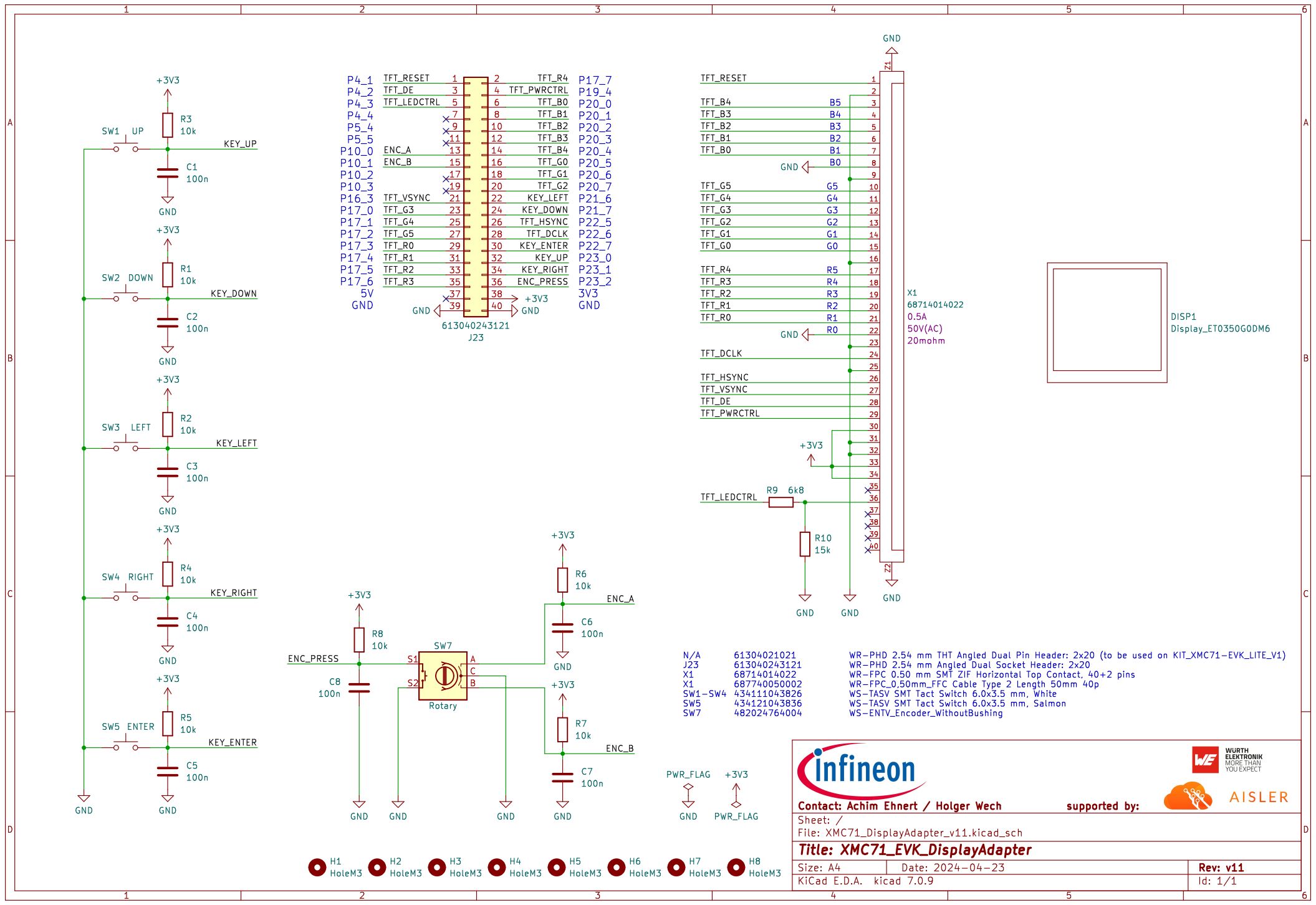
While for evaluation data values might be shown on a serial terminal using e.g. UART, for real industrial applications a real display might be useful or may become mandatory. As the controller itself and the integrated peripherals, such as timers, are powerful enough a 'simple' (= controllerless) TFT-display (e.g.: ET0350G8DM6) will be connected and driven directly by pure software.
Bill of Material:
- Display (320 x 240) ET0350G8DM6
- WR-PHD 2.54 mm Angled Dual Pin Header, 61304021021, provided by Würth
- WR-PHD 2.54 mm Angled Dual Socket, 613040243121, provided by Würth
- WR-FPC 0.50 mm SMT ZIF Top Contact, 68714014022 provided by Würth
- WR-FPC_0, 50mm_FFC Cable, 50mm, 687740050002 provided by Würth
- WS-ENTV_Encoder_WithoutBushing, 482024764004 provided by Würth
- WS-TASV SMT Tact Switch White, 434111043826 provided by Würth
- WS-TASV SMT Tact Switch Salmon, 434121043836 provided by Würth
- The raw PCB can be ordered from PCB manufacturer Aisler here.
On both boards J23 (WR-PHD 2.54 mm Angled Dual Pin Header and socket) needs to be assembled for the connection.
A basic software example has been developed using Infineon's free IDE ModusToolbox(TM) to configure the microcontroller and its peripherals which is required to access to the display. This is on top the DMA-triggered timers which are used for generation of the required control signals.
For details, please open the Device Configurator of the given project example.
Besides the signal generation to drive the display, the Light and Versatile Graphics Library (LVGL) is used to create the visuals. In this project example mainly some demos and test content of LVGL are used to demonstrate the adapter's usage.
Getting started & DemonstrationFor testing, the integrated test bench of LVGL has been used.
A further code example, like a Pong-style game, is realized (thanks to Caio) to verify the usability.
The project features a simplified, single-player version of the classic game Pong which consists of four screens. Upon powering up the board, the title screen is displayed for a few seconds showing the logos of Infineon and our partner companies who assisted in creating the custom XMC71_EVK_DisplayAdapter_V11 board. After the title screen, users can navigate between two modules: the help screen module and the Pong module.
The help screen provides details on the available user inputs:
- RIGHT button: Starts the game module and restarts it in case of a game over.
- LEFT button: Takes the user to the help screen.
- Rotary encoder: Controls the paddle in the game.
The game screen displays the actual game and, if the player loses, a game over screen is shown.
Here is the software's flow chart:
Details of the code example 'XMC71_EVK_DisplayAdapter_SoloGame'
The button inputs are managed by interrupts, which set a flag for each button press. By contrast, the encoder data is polled according to the implementation in the LVGL library. The polling period matches the screen refresh period, defined by the LV_DEF_REFR_PERIOD macro in drivers/lvgl/src/lvgl_conf.h
The Pong game logic consists of two states:
1. PONG_PLAY: In this state, the paddle positions are updated based on user inputs and collisions are managed. The game also checks for a game over condition, setting the gameOver flag when the paddle fails to hit the ball.
2. PONG_OVER: In this state, the player is shown the game over screen, with text indicating the end of the game and how to restart, and gameOver is cleared.
In addition to lv_timer_handler() and Cy_SysLib_Delay(), which support the appropriate functioning of LVGL, the infinite loop of the program includes a function called runAndUpdateGameState(). This function uses a switch/case structure to manage the states illustrated in flowchart shown above. It handles transitions between states and calls the appropriate functions to render each screen on the display.
This project demonstrates a low-cost solution to add a display to a high-performance microcontroller like XMC7100 by the implementation of software to generate the required graphic signals for a graphic-controllerless display.
Any graphics library, e.g. LVGL, can be used on top for the realization of the graphic content, e.g. a game or a human-machine-interface (HMI).
Special thanks to Aisler for manufacturing the PCBs and to Würth Elektronik for providing the collateral parts.
Very Special thanks to Caio for his software support and code example development of this project.


Comments
Please log in or sign up to comment.