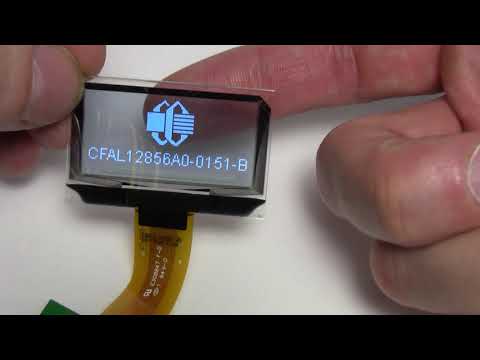
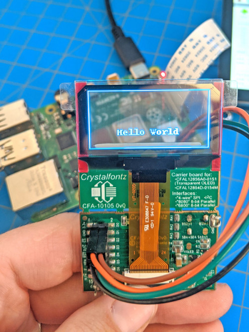
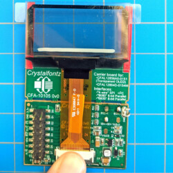
Brand new, cutting-edge transparent OLED display! Also known as TOLED. 128x56 1.51 inch! As you can see from the images this OLED is super-bright, monochrome display. The pixel color is a light-blue when lit and about 70% transparent when not lit. There are actually 64 rows, however the bottom 8 rows have the "getter" so those pixels aren't viewable from the back.
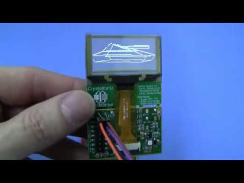
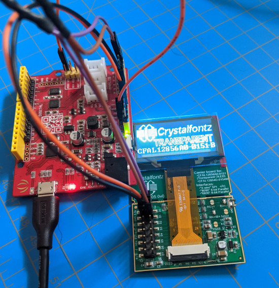
This display supports, parallel, I2c, and SPI interfaces. We powered it up using an 3.3v Seeeduino/Arduino UNO Clone and a small break-out board. This little OLED uses the super common Solomon Systech SSD1309 integrated controller.
Check out the schematic in the datasheet to see how to wire this transparent display to your microcontroller. You'll need a few easily sourced components.
This is a 3.3v device, plugging it into 5v can permanently damage this module.
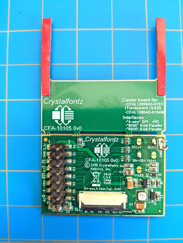
On the right side of the breakout board there is a group of five jumpers. To set the board up to communicate using I2C two of the jumpers need to be closed. You can see that we have simply blobbed some solder to close the two jumpers. This is an engineering sample board, so it’s not as clean as you might hope.
As described on the back of the board, and in the board’s datasheet, the interface selection for I2C is BS1=1 and BS2=0. The breakout board also handles tying D1 and D2 together to serve as SDA when the jumper SDA=SDA is closed.
Step 2: Connect the Transparent Display
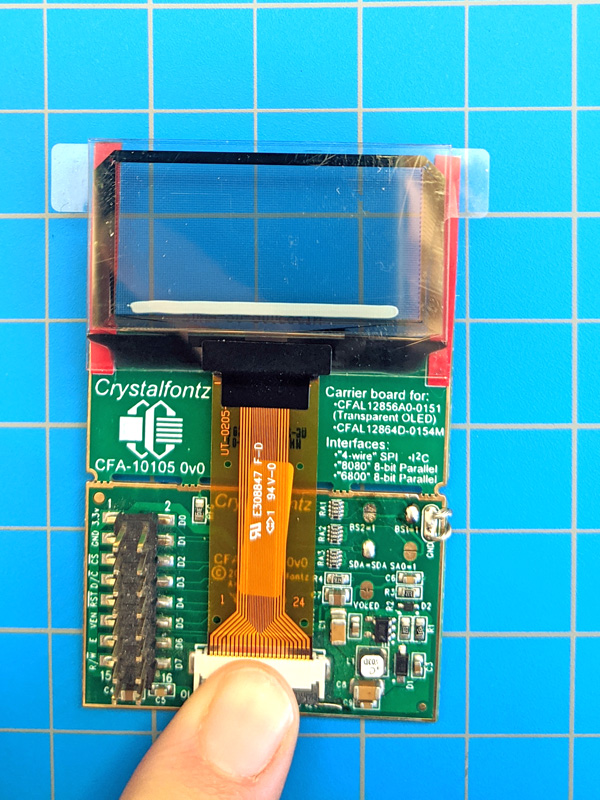
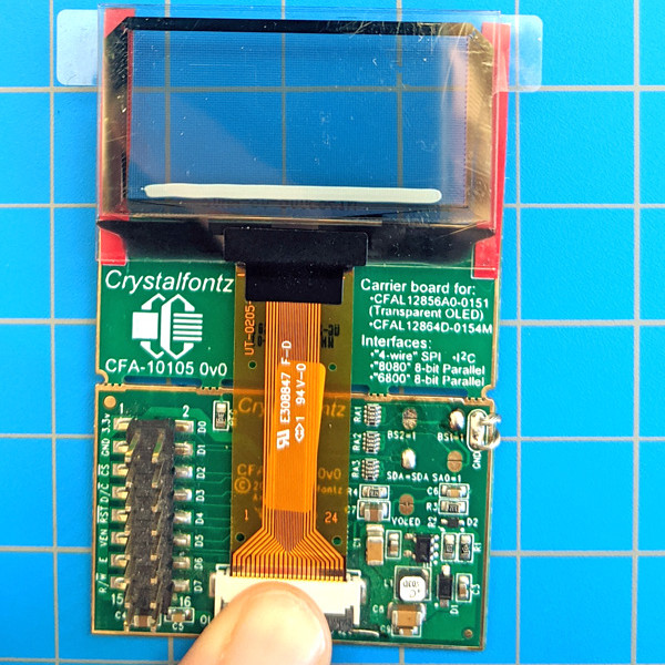
Insert the display tail into the ZIF connector and close the connector
With the shiny pins facing up, gently slide the tail of the display into the ZIF connector. As the name implies, the tail should go into the connector with Zero Insertion Force.
Once the tail is well seated in the connector, close the connector by pressing down on the black hinge.
This would also be a good time to tape the display to the board, if desired. Simply peel the tape backing off, align the display, and press gently down to secure the display.
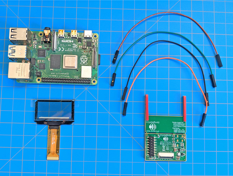
Step 3: Wire the Breakout Board to the Raspberry Pi
Connect Power, Ground, SLC and SDA
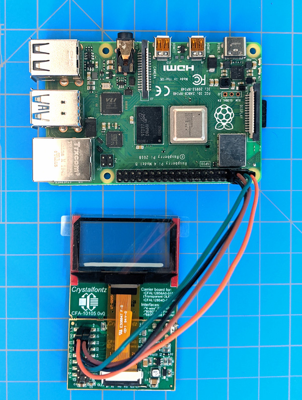
Just four wires are needed to wire the transparent display to the RPi.
Power: The orange wire goes from the 3.3v pin on the breakout board to the 3.3v power on the RPi. We used Pin 1, but any of the 3.3v power pins will work.
Ground: The black wire goes from GND on the breakout board to pin 6 ground on the RPi.
SCL: The brown wire goes from D0 (SCL) to pin 5 (GPIO 3 (I2C Clock)) on the RPi.
SDA: The green wire goes from D1 (SDA) to pin 3 (GPIO 2 (I2C Data)) on the RPi. Or, if you’re feeling weird, you can connect to D2, since the jumper SDA=SDA is closed tying D1 and D2 together.
The RPi has internal pull ups for the I2C pins, so there’s no need to use external pull ups.
Step 4: Install the latest version of luma.OLED
First, make sure I2C is enabled on your Raspberry Pi. You can follow this tutorial to enable it.
We’re going to use the Luma OLED library to get this display up and running. This command will install the latest version:
$ sudo -H pip3 install --upgrade luma.oled
You also need to give them permission to access some hardware interfaces, where “pi” is the name of the account you’ll be using (the default is “pi”).
If changing the interface on the breakout board isn’t an option, change the code to use SPI instead. Make sure SPI is enabled on your Pi. Then import “spi” instead of “i2c” and define serial as “spi(device=0,port=0)”.
You’ll also need to change the wiring a bit. Luma’s documentation includes a nice SPI wiring table, though you’ll ignore the pin numbers for the display. It’s also nice to look at the Raspberry Pi pinout to remember that GPIO numbers are not the same as the pin numbers on the RPi.
Bringing up Other OLEDs on Raspberry Pi
This tutorial can be followed exactly for our three OLEDs that pair with the CFA10105 breakout board: the transparent OLED, a white OLED, and a yellow OLED.
The luma.OLED library interfaces with many OLED controllers (SSD1306, SSD1309, SSD1322, SSD1325, SSD1327, SSD1331, SSD1351, SSD1362, SH1106, and WS0010), so with a few adjustments (changing the device define to match your display’s controller, and having a compatible breakout board) this tutorial can be used for many of our OLED displays.
If you have any questions, reach out to support@crystalfontz.com. We also provide chat and telephone support Monday through Friday during our open hours.
We love to hear about your projects! If you bring up a transparent OLED on raspberry pi, let us know! Find us around the web (YouTube, Facebook, Instagram, LinkedIn, Twitter, Forum) and let us know what you’re working on.
Kelsey is an engineer at Crystalfontz. She graduated from Gonzaga University with a BS in Electrical Engineering. Kelsey’s roles at Crystalfontz include product design, custom parts, customer support, documentation, and product demonstrations.
What our customers say about Kelsey:
“As a new user to the world of LCD electronics, Kelsey has been a Godsend in providing the hand-holding I needed to get my project up and running despite my own efforts at fouling things up! :-)” – Owen M
“Kelsey got me through changing code for a new LCD in only two short emails.” – Phillip V
“The agent that I talked with (Kelsey), is technically sound and she knows what she is doing. The support is what made my job easier to get started with the different display technologies. Thank you!” – Vatsal S
I have the kit and reuploaded the code and now it’s not working
1.Check that you have the correct interface defined in the code. The kit ships set up for SPI, so SPI should be defined.
// Select the interface
#define SPI_4_WIRE
//#define PAR_8080
//#define I2C
2. Check that none of the wires have come loose. A pin table can be found in the getting started guide.
3. Check that the display is in the breakout board correctly. The shiny pins on the display tail should point up when placed into the ZIF connector on the board.
How do I get it working with I2C?
The CFA10105 board ships with all the jumpers open, which means it’s set up to communicate using SPI. To switch the interface, refer to the interface selection table (in the datasheet and printed on the back of the board). When the BS jumpers are open, BS1/BS2 are low (0). Close the appropriate jumper to tie either line high as indicated in the interface selection table.
For I2C, close the BS1=1 jumper and leave the BS2=1 jumper open. Our demo code uses SDA, so tie SDI and SDO together by closing the SDA=SDA jumper.
Then, wire the CFA10105 to the Seeeduino: power to power, ground to ground, RST to D9, D0 to A5, D1 (or D2) to A4. Don’t forget to use pull-up resistors on the clock and data lines.
Make sure I2C is the defined interface in the code, and upload it:
// Select the interface
//#define SPI_4_WIRE
//#define PAR_8080
#define I2C
Can I make glasses?
Sure, we’re not going to stop you! But when a display is placed close to the eye, special lenses and optics are needed to be able to focus on the display. You’ll likely give yourself a headache trying to read anything displayed on these displays at a glasses distance.
Are there any plans to make higher resolution transparent OLED displays? A larger size? A flexible version? A curved version?
At this time we have no plans to add to our transparent OLED product line. If you are looking for production quantities (>5,000) send us an email. If you’re looking for smaller quantities, send us a note in the forum about what you’re looking for. If enough people are interested in a display with the same characteristics, we may look in to expanding our selection.
Can you move the tail? Can I get a longer tail? Shorter tail?
Changing the tail would be a complete redesign of the display. It would probably require a 10,000 piece first order.
Can the transparent display be used outdoors?
The brightness is a bit low to be called sunlight readable, but the display has a very high contrast ratio which helps.
If you look at the display directly, it is readable in sunlight, but it becomes unreadable at a small angle. It is invisible against a blue sky background.
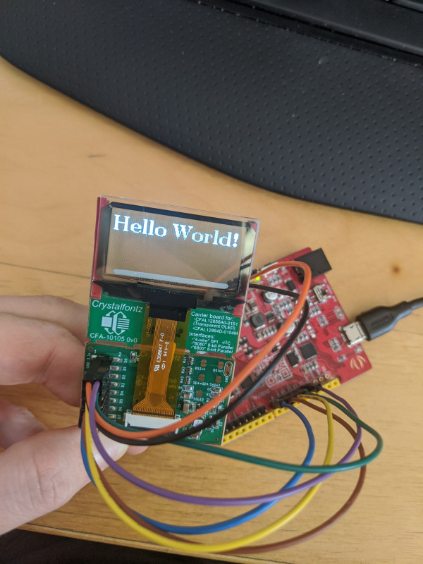
How can I send text using the Arduino IDE?
The easiest way to display text on the transparent will be to use the u8g2 library. It can be installed in the Arduino IDE and is pretty simple to use.
After installing the library, run this sketch for a hello world right away. Note the pinout used in this sketch is a bit different from what’s used in our demo sketch. The pins are defined in the constructor.
#include <Arduino.h>
#include <SPI.h>
#include <U8g2lib.h>

/* Constructor */
U8G2_SSD1309_128X64_NONAME2_1_4W_SW_SPI u8g2(U8G2_R0, /* clock=*/ 13, /* data=*/ 11, /* cs=*/ 10, /* dc=*/ 9, /* reset=*/ 8);
/* u8g2.begin() is required and will sent the setup/init sequence to the display */

void setup(void) {
u8g2.begin();
}

/* draw something on the display with the `firstPage()`/`nextPage()` loop*/
void loop(void) {
  u8g2.firstPage();
  do {
   u8g2.setFont(u8g2_font_ncenB14_tr);
   u8g2.drawStr(0,20,"Hello World!");
     } while ( u8g2.nextPage() );
  delay(1000);
}
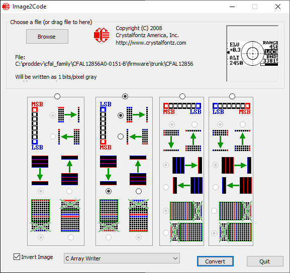
The images in the demo code are in the format 0xYZ where YZ are a combination from A,B,C,D,E,F and numbers from 0-9. Is there a way to decode what the image will be?
The image is stored in a hexadecimal byte array and stored in flash memory.
Since monochrome displays are 1 byte per pixel, you’re basically telling the pixel to be turned off or on.
So your resolution: 128 pixels * 56 pixels / 8 bits per byte = 896 bytes in the array.
This display pages vertically so to learn how it updates, you might try putting a delay after every data byte you send when updating the display.
Images can also be made using our Image2Code program. The settings for an image on the transparent can be seen in the image on the right.
The I2C address can also be set on the CFA10105 using the SA0=1 jumper.
Is the brightness adjustable? Are the screens dimmable?
Yes, they are. The dimming is visible in this video, the word “Crystalfontz” is displayed at high and then lower brightness: https://youtu.be/bpruKM6-TDE?t=280 This is also demonstrated in our demo code.
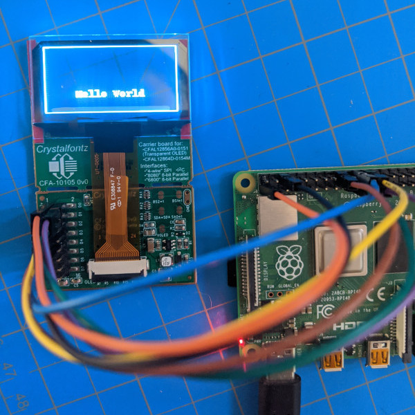
Can you see the contents of the display from the back of the screen or no?
The display is viewable from both sides as can be seen in this video:
The display and board can be driven by any microcontroller. Our sample code is written for Arduino Uno compatible devices. We also have a blog post about using a Raspberry Pi with the transparent OLED. Unfortunately, we cannot help rewrite code for different controllers. Fortunately, the controller used in the transparent OLED (SSD1309) is pretty common.
It’s important to note that the transparent OLED is a 3.3v device. Connecting it to 5v power or I/O lines can permanently damage the display. Read more about voltage levels and displays.
Contact Us
If you have any questions, we can be reached at support@crystalfontz.com, we also provide chat and telephone support Monday through Friday during our open hours.
Kelsey is an engineer at Crystalfontz. She graduated from Gonzaga University with a BS in Electrical Engineering. Kelsey’s roles at Crystalfontz include product design, custom parts, customer support, documentation, and product demonstrations.
What our customers say about Kelsey:
“As a new user to the world of LCD electronics, Kelsey has been a Godsend in providing the hand-holding I needed to get my project up and running despite my own efforts at fouling things up! :-)” – Owen M
“Kelsey got me through changing code for a new LCD in only two short emails.” – Phillip V
“The agent that I talked with (Kelsey), is technically sound and she knows what she is doing. The support is what made my job easier to get started with the different display technologies. Thank you!” – Vatsal S