#include <Adafruit_GFX.h>
#include <Adafruit_SSD1351.h>
#include <Servo.h>
#include <math.h>
//Screens dimensions
#define SCREEN_WIDTH 128
#define SCREEN_HEIGHT 128
//the oled screen's inputs
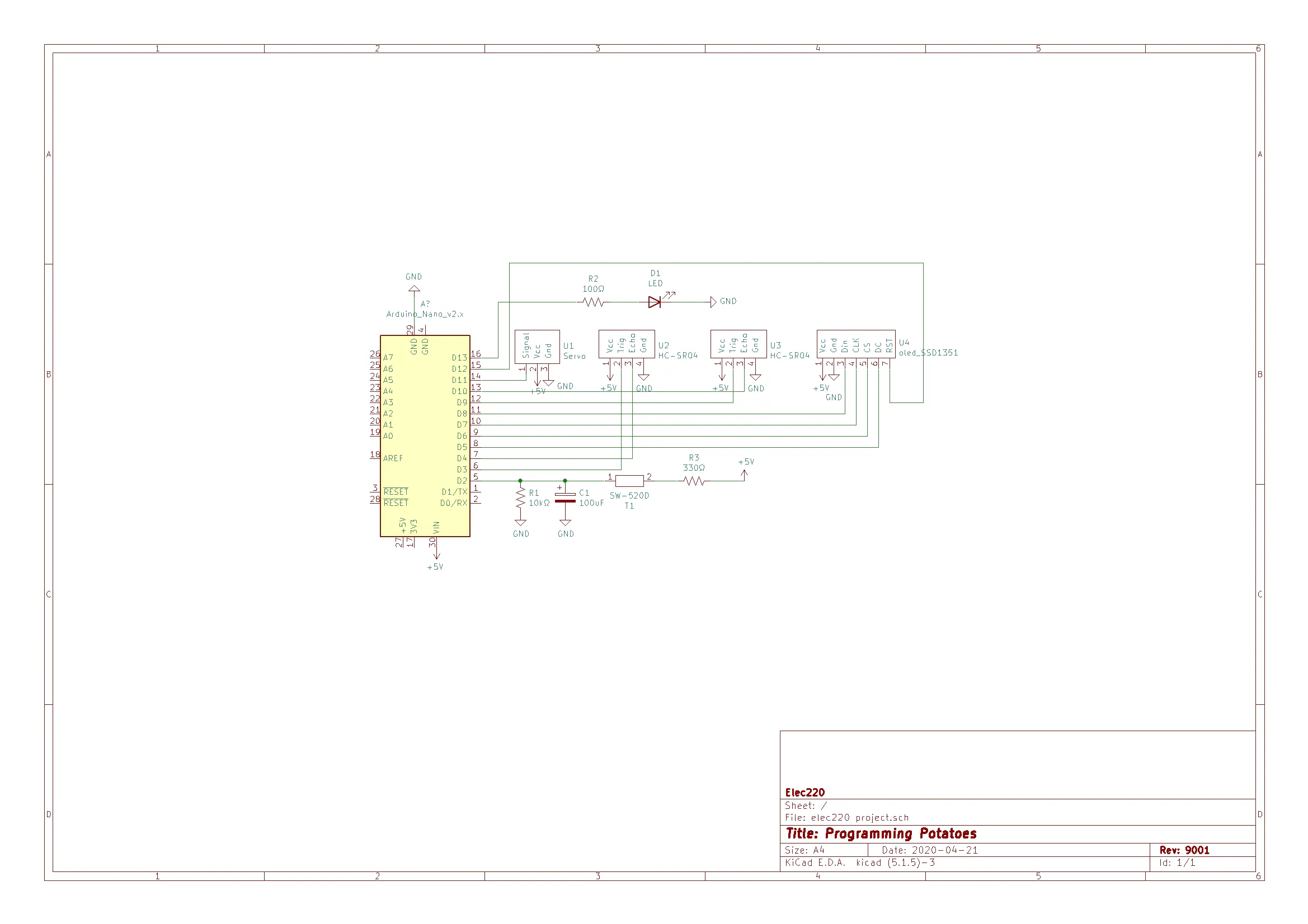
#define MOSI_pin 8 //Din
#define DC_pin 5 //DC
#define CS_pin 6 //CS
#define SCLK_pin 7 //CLK
#define RST_pin 12 //RST
//oled screen's 16-bit color values that are used in the project
#define WHITE 0xFFFF
#define BLACK 0x0000
#define GREEN 0x0FE0
#define RED 0xF800
//#define CYAN 0x07FF //;-;
#define led_pin 13 //fight me on my naming schemes
//pins of the ultrasonic sensors
#define trig_pin_0 9
#define echo_pin_0 10
#define trig_pin_1 3
#define echo_pin_1 4
#define tilt_pin 2
//Servo initialization
Servo servo_0;
//Screen initialization
Adafruit_SSD1351 oled_screen = Adafruit_SSD1351(SCREEN_WIDTH, SCREEN_HEIGHT, CS_pin, DC_pin, MOSI_pin, SCLK_pin, RST_pin);
float sensor_0_dist, sensor_1_dist, scaled_dist;
int x,y;
//desired max circle radius on the screen in pixels
const int circle_rad = 50;
//desired distance plotting cutoff: anything past this in cm is not plotted
const int max_sensor_dist = 40;
int pos = 0;
void setup() {
Serial.begin(9600);
servo_0.attach(11);
oled_screen.begin();
pinMode(tilt_pin, INPUT);
pinMode(led_pin, OUTPUT);
pinMode(trig_pin_0, OUTPUT);
pinMode(trig_pin_1, OUTPUT);
pinMode(echo_pin_0, INPUT);
pinMode(echo_pin_1, INPUT);
attachInterrupt(0,tilt_interrupt,LOW);
servo_0.write(0);
}
void loop() {
oled_screen.fillScreen(BLACK);
oled_screen.fillCircle(SCREEN_WIDTH/2 - 1, SCREEN_HEIGHT/2 - 1, 3, GREEN);
oled_screen.drawCircle(SCREEN_WIDTH/2 - 1, SCREEN_HEIGHT/2 - 1, circle_rad, GREEN);
rotate_measure(3);
oled_screen.fillScreen(BLACK);
oled_screen.fillCircle(SCREEN_WIDTH/2 - 1, SCREEN_HEIGHT/2 - 1, 3, GREEN);
oled_screen.drawCircle(SCREEN_WIDTH/2 - 1, SCREEN_HEIGHT/2 - 1, circle_rad, GREEN);
rotate_back_measure(3);
}
void move_servo(int final_pos){
/*
* Since the servo that was used is not a great servo or not enough power
* is being supplied, the servo jitters or overshoots. This method takes
* the desired final position as an input and slowly increments to the final
* position in an attempt to reduce jittering and overshoots.
*
* Inputs:
* final_pos - the final location of the servo that is desired
*/
if (final_pos > pos){
for (int i = pos; i <= final_pos; i++){
servo_0.write(i);
delay(100);
}
}
else if (final_pos < pos){
for (int i = pos; i >= final_pos; i--){
servo_0.write(i);
delay(100);
}
}
else{
servo_0.write(final_pos);
delay(100);
}
pos = final_pos;
}
void rotate_measure(int angle){
/*
* This function, rotate, rotates the servo from 0 to 180 degrees incrementally by angledegrees,
* plotting the distance of any object in the direct line of sight at each incremental angle
* There are two ultrasonic sensors to capture all of the nearby surroundings.
* Inputs: angle, an integer that represents the size of the incremental rotations.
*/
for (int degree = 6; degree < 180; degree += angle) {
//Tell the servo to rotate however many degrees
move_servo(degree);
//Wait time in milliseconds for the servo to reach the position
delay(500);
//mapping is required as the servo's physical zero position is not actually at zero degrees. More so at 6 degrees.
//int actual_deg = map(degree, 6, 179, 0, 179);
//Adds degrees to plotList (this is for sensor0)
sensor_0_dist = get_distance(trig_pin_0, echo_pin_0);
delay(200);
//Adds degrees to plotList (this is for sensor1)
sensor_1_dist = get_distance(trig_pin_1, echo_pin_1);
plot(degree, sensor_1_dist, angle);
plot(degree + 180, sensor_0_dist, angle);
}
}
void rotate_back_measure(int angle){
/*
* This function, rotateBack, rotates the servo 180 degrees incrementally by angle degrees,
* recording the distance of any object in the direct line of sight at each incremental angle through 360 degrees in plotlist. There are two ultrasonic sensors to capture all of the nearby surroundings.
*
* Inputs:
* angle, an integer that represents the size of the incremental rotations.
*/
for (int degree = 179; degree > 5; degree -= angle) {
//Tell the servo to rotate however many degrees
move_servo(degree);
//Wait time in milliseconds for the servo to reach the position
delay(500);
//mapping is required as the servo's physical zero position is not actually at zero degrees. More so at 6 degrees.
//int actual_deg = map(degree, 6, 179, 0, 179);
//Adds degrees to plotList (this is for sensor0)
sensor_0_dist = get_distance(trig_pin_0, echo_pin_0);
delay(200);
//Adds degrees to plotList (this is for sensor1)
sensor_1_dist = get_distance(trig_pin_1, echo_pin_1);
plot(degree, sensor_1_dist, angle);
plot(degree + 180, sensor_0_dist, angle);
}
}
float get_distance(int trigPin, int echoPin){
/* This function, getDistance, takes two pins of one ultrasonic sensor and
* calculates the distance of the object detected based on the time recorded. The
* sensors send a high-pitch frequency and record the time it takes for the signal to
* rebound back.
*
* Inputs:
* trigPin, an integer representing the trigger pin (this is an input pin that triggers the ultrasonic sound pulses).
* echoPin, an integer representing the echo pin (this is an output pin that receives the rebound pulse.
* Output:
* distance, a float which represents the distance of an object in centimeters.
*/
//declare echoTime and dist
float echoTime, dist;
//send pulse for 10 microseconds
digitalWrite (trigPin, HIGH);
delayMicroseconds(10);
digitalWrite(trigPin, LOW);
//get time it takes to receive sent pulse
echoTime = pulseIn(echoPin, HIGH);
//calculate distance in cm
//echoTime in microseconds = 10 ^ -6 s
//Speed of sound 343 m/s = 0.000343 m/ microseconds = 0.0343 cm/micros
dist = (echoTime * 0.0343) / 2;
delay(200);
return(dist);
}
void plot(int degree, int dist, int increment){
/* This function, plot(), plots the distances in plot_list onto the oled screen.
* Inputs
* degree, where the servo's currently at.
*/
//scales the distance received from the ultrasonic sensor into distance away from the center
//to draw the representative pixel.
scaled_dist = dist * circle_rad*1.0/max_sensor_dist;
float theta;
//oled_screen.drawLine(63*cos((degree*PI/180)+PI) + 63, 63*sin((degree*PI/180)+PI) + 63, 63*sin(degree*PI/180) + 63, 63*sin(degree*PI/180) + 63, GREEN);
//draws and undraws the lines on the edge of the outer circle to indicate where the sonar is currently facing
oled_screen.drawLine(63*sin((degree*PI/180))+63, 63*cos((degree*PI/180)) + 63, (circle_rad+3)*sin(degree*PI/180) + 63, (circle_rad+3)*cos(degree*PI/180) + 63, RED);
oled_screen.drawLine(63*sin((degree*PI/180)+PI)+63, 63*cos((degree*PI/180)+PI) + 63, (circle_rad+3)*sin((degree*PI/180)+PI) + 63, (circle_rad+3)*cos((degree*PI/180)+PI) + 63, RED);
delay(100);
oled_screen.drawLine(63*sin((degree*PI/180))+63, 63*cos((degree*PI/180)) + 63, (circle_rad+3)*sin(degree*PI/180) + 63, (circle_rad+3)*cos(degree*PI/180) + 63, BLACK);
oled_screen.drawLine(63*sin((degree*PI/180)+PI)+63, 63*cos((degree*PI/180)+PI) + 63, (circle_rad+3)*sin((degree*PI/180)+PI) + 63, (circle_rad+3)*cos((degree*PI/180)+PI) + 63, BLACK);
//plots the distance on the screen
for (int i = 0; i < increment; i++){
theta = (degree + i) * PI/180.0;
if (scaled_dist > 3 and scaled_dist < circle_rad){ //makes sure that the point its about to plot is within bounds
y = (int) scaled_dist * cos(theta) + 63;
x = (int) scaled_dist * sin(theta) + 63;
//oled_screen.fillCircle(x, y, 1, WHITE);
oled_screen.drawPixel(x,y,WHITE);
}
}
}
void tilt_interrupt(){
/* This function handles the interrupt logic
* it basically turns on an led while the tilt sensor is logically low
*/
//only releases when the sensor is released
while(digitalRead(tilt_pin) == LOW){
digitalWrite(led_pin, HIGH);
delay(50);
}
digitalWrite(led_pin, LOW);
}


_t9PF3orMPd.png?auto=compress%2Cformat&w=40&h=40&fit=fillmax&bg=fff&dpr=2)


_3u05Tpwasz.png?auto=compress%2Cformat&w=40&h=40&fit=fillmax&bg=fff&dpr=2)
Comments
Please log in or sign up to comment.