We have all seen remote patient monitoring systems and health trackers, we have seen customized apps that can send alerts or notifications when critical vital signs are recorded. Healthcare automation has always been a popular topic among medical professionals and public, but now, amid this pandemic, it is a necessity and it is always a necessity in places where there is lack of medical professionals and health care providers.
Aim/ ObjectiveI am going to build a Health Network which will connect the patients vital measurement data and feed them to the Health Network device. The data will then be displayed in the app. This could be a new introduction to healthcare automation and would also require less medical professionals and healthcare providers.
This is useful because it is quick and efficient. It reduces the demand for healthcare providers and professionals which is a great advantage for places that lack sufficient healthcare workers. Using this method of healthcare automation would mean that the number of medical professionals and healthcare providers, like doctors and nurses, present per ward will be reduced and this will be essential as the healthcare professionals will be able to attend more patients who require urgent medical care instead of those who require regular monitoring. This system will be helpful in places where there is lack of medical professionals.
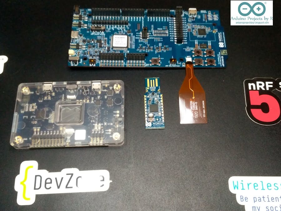
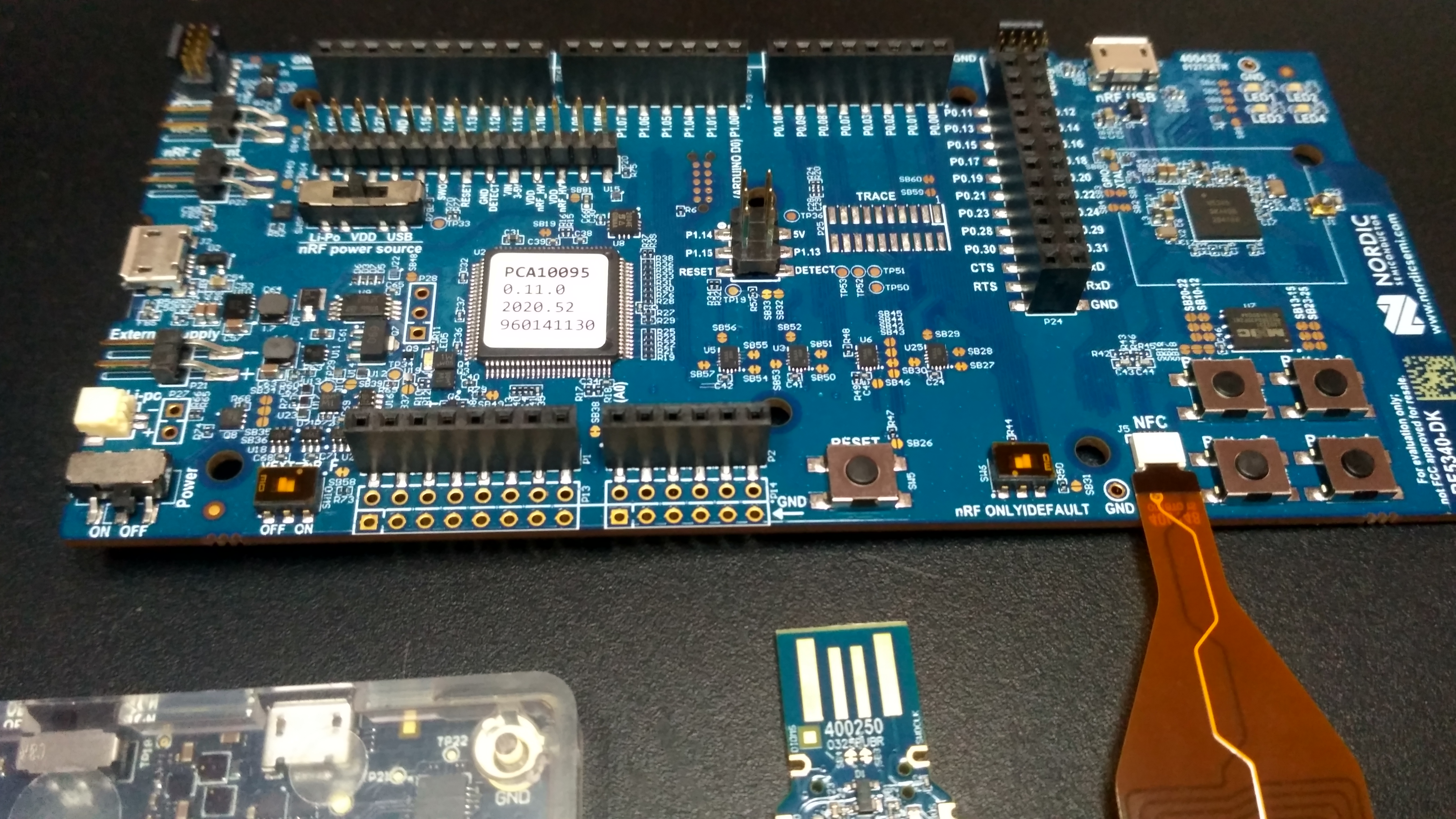
Hardware components required for this project- Nordic Semiconductor nRF5340 DK
- Power profiler kit II
- nRF52840 Dongle
- Arduino Nano R3
- Bluetooth module (HC-05)
- nRF connect SDK
- MIT Inventor app
- Arduino IDE
The device will be synced with the app and the app will be used by the medical professional in charge of the ward. Notifications are sent from the app when a critical value is recorded, and the healthcare professional will be alert.
The device will be connected to the Electronic medical records (EMR) system of all patients via Bluetooth mesh. The nRF52840 Dongle will be utilized to extend the range of Bluetooth connectivity and enhance the function of the device. The Power Profiler Kit II will be used to monitor the power consumption of the device which will be powered by a Li-Po battery. The Arduino Nano R3 development board and the Bluetooth module will be used to connect each patient's EMR system with the device via Bluetooth mesh.
Setting up nRF Connect SDKI followed the instructions provided in this tutorial to set up the nRF Connect SDK.
- Install the Toolchain Manager app
- Install the latest SDK
- After the installation is complete, read the 'First steps to build' and open the IDE.
- You will also need to install the power profiler app.
The nRF5340 DK board comes with the Blinky code installed on it for debugging purposes but I would like to demonstrate the steps to run the example Blinky project.
Let us check if the board works properly.
Connect the board to a power supply and you will see the LED light up on the board.
On the bottom right corner, you will see four push-buttons. Try pressing on each of the push-buttons to see how they function.
You can view the demonstration here:
Now let's try uploading the code to your nRF5340 DK board.
- Go to File and select OpennRFConnect SDK Project...
- Choose blinky as the project and nrf5430dk_nrf5340_cpuapp as the board.
- Choose your preferred Build directory
- Build the project hex file
- Connect the board to your laptop/ PC and connect it to the IDE
- Download the hex file to the board
Modify the blinky project to make this device compatible with the aim of this project.
The device must be able to connect with the app.
Coding for the Arduino Nano R3You will need the SoftwareSerial library for this section. The github repository containing the library and the documentation can be found in the Code section of this page.
The BP monitor and other electronic health monitoring machines will be connected to the Arduino Nano as I2C peripherals. If you are using more than one machine, you should use an MCP23017 I/O expander to connect many I2C devices to one Arduino Nano microcontroller board.
AppI will be using the MIT App Inventor 2 to create my app for this project. The app will work with Bluetooth devices and control IoT systems as well.
Steps to create apps can be found here: http://iot.appinventor.mit.edu/#/students/intro
Power Profiler Kit IIThe Power Profiler Kit II (PPK2) is a standalone unit, which can measure and optionally supply currents all the way from sub-uA and as high as 1A on all Nordic DKs, in addition to external hardware.
The PPK2 is powered via a standard 5V USB cable, which can supply up to 500mA of current. In order to supply up to 1A of current, two USB cables are required.
An ampere meter only mode, as well as a source mode (shown as AMP and source measure unit (SMU) respectively on the PCB) are supported. For the ampere meter mode, an external power supply must source VCC levels between 0.8 and 5V to the device under test (DUT). For the source mode, the PPK2 supplies VCC levels between 0.8 and 5V and the on-board regulator supplies up to 1A of current to external applications. It is possible to measure low sleep currents, the higher active currents, as well as short current peaks on all Nordic DKs, in addition to external hardware. [source]
To use the power profiler kit II to measure the power consumption of the Nordic Semiconductor nRF5340 DK, you have to install the Power profiler app.
Power up your power profiler kit II after connecting it to the Nordic Semiconductor nRF5340 DK. You can see the visualization of the nRF5340 DK current consumption in the Power profiler app.
Improvements for this project- Extend the Bluetooth range for the wearable.
- Convert this device into a wearable.
- Convert this into a lower power consumption device.


Comments
Please log in or sign up to comment.