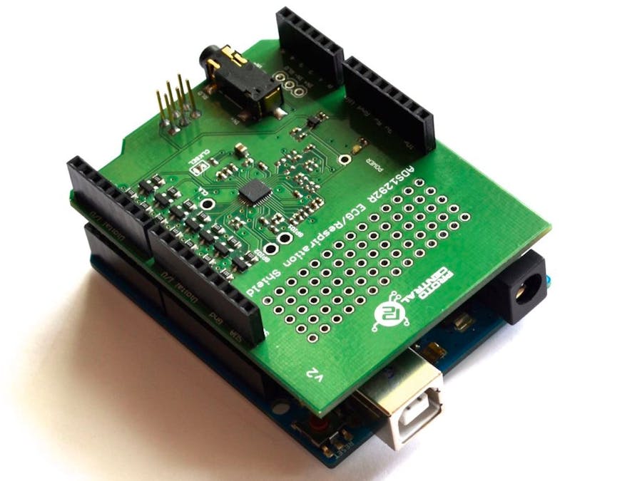
The ECG respiration shield takes a medical device to another level. What seemed like a complicated system for monitoring the electrical activity of the heart has taken a new form. The new device is portable, less complicated and an efficient ECG monitoring system. This project helps to showcase how to use the ECG shield along with Arduino.
Connecting the shield to your ArduinoConnect the ECG/Respiration shield to the Arduino by stacking it on top of your Arduino. This shield uses the SPI interface to communicate with the Arduino. The shield includes ICSP header, used by newer Arduino variants for SPI communication, and hence is compatible with the newer Arduino variants such as the Yun and Due.
Installing the Arduino librariesThe Arduino library contains the functions required to communicate with the ADS1292R Shield. Please follow the steps below to download and get the library working.
Download the library files from the here. Unzip the archive and you should see a folder by name "ads1292r_shield". Copy this folder onto your Arduino IDE’s libraries folder. Depending on your operating system, this could be either within your Arduino IDE’s folder or your documents folder. For more information on folder structures, please refer http://arduino.cc/en/Guide/Libraries.
For use with earlier BrainBay and Xively examples click here.
Using Processing - Data Visualisation Software (New!)
Processing is a data visualisation software, in existence since 2001, used by artists and scientists alike. Its an open source coding framework based on Java. If you are familiar with the Arduino environment, the Processing IDE is similar and you wont have much of a learning curve to climb!
Note: The code for ECG visualisation is executed using processing IDE version 2.2.1 only.
The following are the steps to run the code:
1. Download Processing for your operating systemDownload the processing IDE version 2.2.1 from the link:
Once downloaded, unzip the archive and install the app as per your OS.
2. Download the Processing code for ECG visualisation- Download the necessary files & directories or clone to your desktop from GitHub.
- Unzipping the archive should make a folder by name ads1292r_shield that contains the visualisation code.
- Locate the Processing sketchbook directory on your computer. This should have been created automatically when you installed processing. Depending on your operating system, the path will be as follows:
- On Windows: c:/My Documents/Processing
- On MAC: /Users/your_user_name/Documents/Processing
- On Linux: /Home/your_user_name/sketchbook/
Note: This directory appears as "Processing" on Windows/Mac, and goes by the name "Sketchbook" on Linux. Create a subdirectory by name "libraries if one doesn't exist already.
- From the above mentioned "ads1292r_shield" directory Copy/Move the contents of the ADS1292rShield_BreakoutProcessingces_view_ecg folder to the Processing sketchbook directory which is also mentioned above (Locate the Processing sketchbook)
- Finally, copy the controlP5 & gwoptics folders from ADS1292rShield_BreakoutProcessinglibraries and paste them into the libraries directory of your Processing sketchbook.
- You are all set now to get your first ECG reading visualised from the ADS1292R shield!
- If Processing IDE was open, close it and reopen to refresh the libraries and sketches. The repositories are not refreshed if the IDE was open while the Sketches and Libraries were being updated.
- Double-click any of the .pde files in the ces_view_ecg directory to open all of the ecg code in the Processing IDE.
- If everything done so far was good, clicking the "run" button on the top left corner of the IDE, should run the code! If it does not, make sure you installed your libraries correctly and are using version 2.2.1 of Processing.
- d. Once the GUI is running, select the port connect with ECG from the "SELECT PORT" dropdown as shown in the figure below
- Once the port selection is appropriate the START button gets enabled. Click "START" to initiate visualization
- You should see the ECG wave generated with the values obtained from the ADS1292rShield Breakout Board as shown below.
A 3-electrode cable along with a standard stereo jack is provided along with the shield. You may use the electrodes along with the cable to connect to the shield. The onboard electrode interface is highlighted below for easy location.
The other side of the electrode connector would connect to snap-on electrodes attached to the body. For testing purposes, you can use an ECG simulator to provide input to the board.
Warning: When connecting the electrodes to the body, it is safer to disconnect the main/power source to the Arduino. For example, if you are using the Arduino along with a laptop, disconnecting the battery charger from the laptop would be a safe option.
Placing the Electrodes on the bodyImportant Notice: This device is NOT intended to be used in/as medical diagnostic equipment. This is intended to be used solely for evaluation and research purposes only.
Safety Warning: Be careful while connecting the electrodes to the body when the Arduino in plugged in to your computer's USB port. Make sure that your laptop's main power is disconnected so that you don't provide a direct connection between ground and your body.


_ztBMuBhMHo.jpg?auto=compress%2Cformat&w=48&h=48&fit=fill&bg=ffffff)


Comments
Please log in or sign up to comment.