After much arm twisting(we just had to ask), the company I work for installed a couple of kegerators in the break room. There was enough room for 4 slims or two normal sized kegs. They are actually half kegs, but most just call it a keg.
The breakroom is also part of our training facility. We also host a large number of users groups. Being a company of geeks, a few of us started coming up with ideas on how to track the beer consumption. There were a lot of idea thrown about, but I was the one to take action. So this is first of the Beer Trackers. Not sure if this the best idea, but I decided to build a couple and see which works better.
I had some constraints:
- I needed to be able to scale this project to accommodate up to 4 different kegs at the same time.
- Keep most if not all the component parts out of the wet areas
- Have a minimal height increase. Can't have any kinked beer lines. There would be a lynching.
After some research, I found that most digital scales use some form of load cell. A lot of people refer to these things as strain gauges. The basic circuit for a wheatstone bridge is:
The idea is that you put an Excitation voltage across the top and bottom, and measure the voltage at the centers. When everything is in balance, the Sense voltage is 0V. If any of the resistances change, then there will be a voltage change at the center. We can measure that and turn it into something useful.
1. Obtain yourself an inexpensive digital scale. I found this one at Fry's electronics for about $10 on sale:
Turns out that this scale is just about perfect for the slim style keg.
2. Open up the scale. there were a couple of screws and the bottom snapped on. After removing screws, I used a couple of pry bars from a cell phone tool kit. These thing can be a bit tricky as there were really not meant to be taken apart. Just take your time and as a favorite chef of mine says "your patience will be rewarded".
With the cover removed off the bottom, you can see all the electronics, and the load cells.
Notice that there are 3 wires leading from the load cells. These are an indication that each of these is a load cell known as a "half-bridge" load cell. Each one makes up one half and a normal bridge circuit. We have four of them to deal with. If you hook them up in the right they will form a full bridge. Once we have that then we can put a voltage across the bridge and measure the change.
Here is the schematic(from SparkFun):
Luckily, SparkFun has this already figured out for us with this Load Combinator.
3. Take out all the electronic and leave the load cells. A couple of neat parts in there that you maybe able to reuse. Now just match up the load cells read, white, and black wires to the corresponding locations on the Load Combinator. LR = lower right, LL = lower left, UR = upper right, UL = upper left.
The wire are really small and I had a hard time making sure to solder them well and not tear them apart. Take your time and have patience.
4. I really wanted to use the RJ45 module on this board, but my scales were too short.
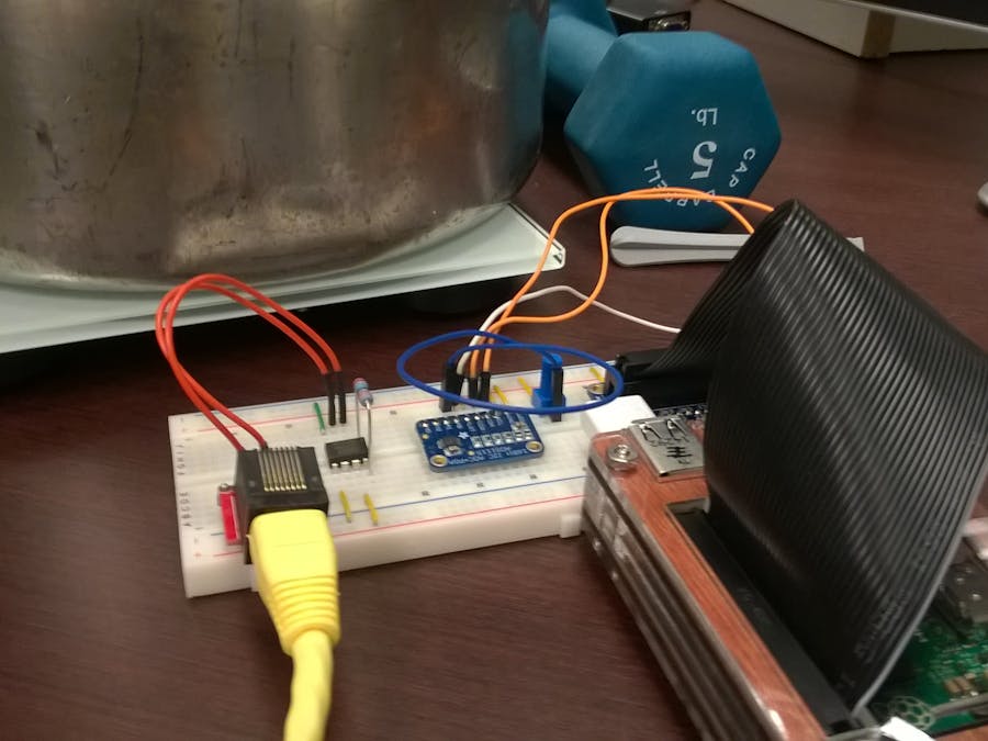
So I cut off the end of prewired ethernet cable. Just connected them pins 1-8 in the appropriate holes. When you get done you should have something like this:
5. If you purchased the RJ45 module separately (like I did), put those parts together. Mount the module in a breadboard and get a voltmeter. At this point, you should be able to test you work. If you put a voltage across pins 7 and 8, and a meter set at the most sensitive setting on pins 4 and 5, then stepping on the scale should produce a voltage change. It will not be much of a change, but it will be measurable. If you get a negative voltage, just switch the wires around.
6. Now we need to amplify that voltage to some useable range. The standard way to do this is with and instrumentation amplify. These things are amazing. They can easily take a small voltage change and amplify it with very little noise 10, 100, or even 10000 times depending on the discrete. The basic circuit for one of these looks like:
There are a number of popular ones out there. I choose the INA114. It was more expensive than the very popular AD620. I found it easier to work with and the AD620 really likes to have a secondary rail for a negative supply. Since we are really only working with a single positive supply, the INA114 was easy to setup that way. If you really want the cheaper chip, go with the AD623. It does that same thing, but is designed to work with a single positive voltage supply.
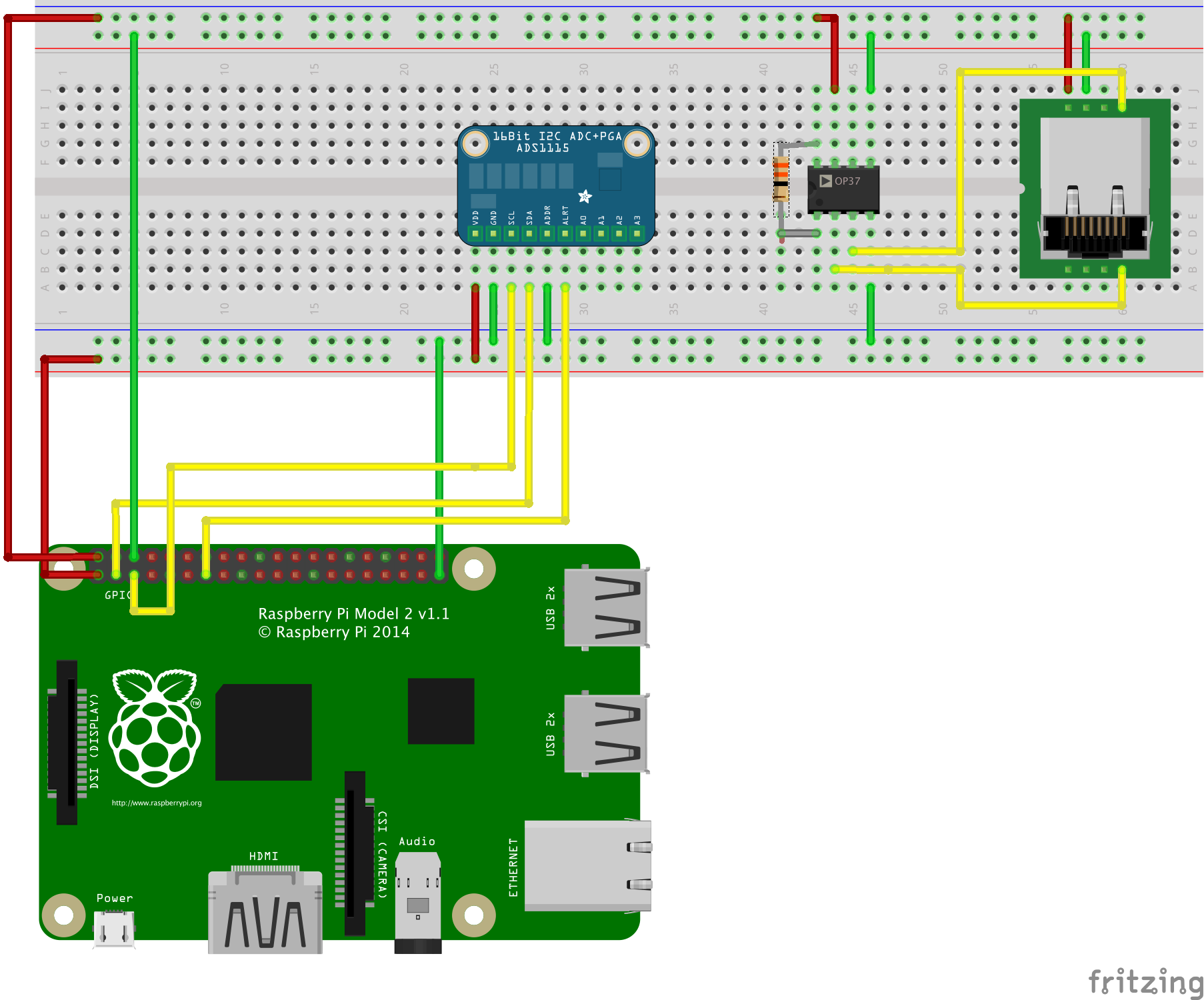
One of the main things you have to do set the gain on the amplifier. This is accomplished by inserting a resistor between pins 1 and 8. There is a chart on the datasheet that gives you a number of examples of resistance values and the multiplication factors.
I went with a 1500 multiplication factor, which required a 33 ohm resistor.
Once you have the instrumentation amp hooked up, you should be able to measure a good bit of voltage change. Seems all the amp have a compatible pinout, so put a volt meter on pin 6 and ground. You may get a voltage while doing nothing. I know I did. I had 0.62 volts with nothing connected. Haven't figure out what to do about that yet.
Then with RJ45 pins connected up, step on the scale and notice that the voltage really moved this time. Make sure you set your voltmeter high enough to handle your V max.
7. Next is the analog to digital part. I used the ADS1115 from Adafruit. This is thing is crazy sensitive and is way more than this project needs. However, it does have some nice features that I took advantage of.
https://www.adafruit.com/products/1085
I fed pin 6 from the INA114 in to A0 pin on the ADS1115. Connect the ADDR0 pin to ground giving use the 0x48 address for the I2C. Connect up the SDA, SCL, VDD, and GND to the respective places. I also connected the ALRT pin to GPIO27, so that I would not have to poll the chip. That line changes state when a value is ready to be read.
For testing of the ADS1115, I put in a simple potentiometer and drove pin A0 off the sweeper. It allowed me to play with the settings at various level before hooking everything up.
At this point is time to start coding.
The program follows the standard pattern:
- Initialize the GPIO and I2C controllers
- setup the ADS1115
- show the initial screen
- Read the data.
8. Calibration time. I put a known weight on the scale got good movement on the A0 line. Noted the number that appeared with the weight. Took the weight off and noted what was left. Below are the calculations that I came up with:
Seems I am getting about 0.2 oz/tick. That's crazy accuracy. I know the standard scale doesn't report to that level.
There are some problems with this through.
- I believe that I am way too sensitive.
- I was expecting very linear changes, I don't believe I have that here. I don't have enough known weights to get a proper set of data going.
Final Thoughts:
This a fun figuring out stuff I haven't thought about since college. With the 4 possible analog channels, I will get all the kegs tracking.


_3u05Tpwasz.png?auto=compress%2Cformat&w=40&h=40&fit=fillmax&bg=fff&dpr=2)
Comments
Please log in or sign up to comment.