Servo motors / Robotic Arms are controlled using buttons and encoders. I'd want to use PSoC4100 to control the servos using Capacitive Sensing. I'll be building a camera controller - servo mounted using the PSoC 4100 pioneer kit. The Raspberry Pi Camera is mounted on the Servos that are connected to the Raspberry Pi 3B+. Using Pioneer PSoC 4100 kit gesture control, the servos move the camera's positions.
Hardware - Setting up PSoC 4100SWe have received the PSoC 4100S Pioneer Kit from hackster. The PSoC 4100S device has the fourth-generation, low-power CAPSENSE solution, up to 64KB flash, 8KB SRAM, 9 programmable analogue blocks, 8 programmable digital blocks, 36 general-purpose I/Os, all of which are CAPSENSE capable, and 16 smart I/Os.
Now let's see how to set up the kit. Make sure that you toggle to EXT in the PWT SEL switch. Connect the micro-USB cable to the kitThe basic RGB program has been preprogrammed in the kit. Touch the coloured area (CAPSENSE) to change the colour of the RGB LED. Once you release it, the LED goes off in 3 seconds.
The Raspberry Pi is a powerful computer that allows users to harness the power of a microcomputer while also taking use of general-purpose inputs/outputs (GPIOs). Engineers and producers may easily measure, operate, and monitor equipment thanks to the inputs and outputs. The GPIO pins of a Raspberry Pi will be used to power and operate an SG90 servo motor, which requires pulse-width modulation (PWM) to control the angular rotation about its axis. Python will be used, along with several built-in packages that explain pulse-width modulation. The PSoC and the Raspberry Pi communicate through UART. The servo motors are controlled by the trackpad output from the PSoC.
If you haven't already done so, install PSoC Creator on your computer. This is Cypress Semiconductor's integrated development environment (IDE) for developing and programming PSoC devices.
Select the example project "USB HID Trackpad" for PSoC4100S. You can find example projects in the PSoC Creator software by navigating to the "File" menu and selecting "Code Examples." Choose an example project that is compatible with the PSoC4100S.
Build the example project by selecting "Build" from the "Project" menu. This will compile the source code and generate the firmware binary file.
Connect the PSoC4100S board to your computer using a USB cable. Ensure that the board is powered on. Click on the "Program" button in the PSoC Creator software to program the firmware binary file onto the PSoC4100S. PSoC Creator will automatically detect the connected board and program the firmware onto it.
Once the programming process is complete, disconnect the PSoC4100S from your computer and power it off. Reconnect the board to power it back on and test the functionality of the programmed USB HID Trackpad program.
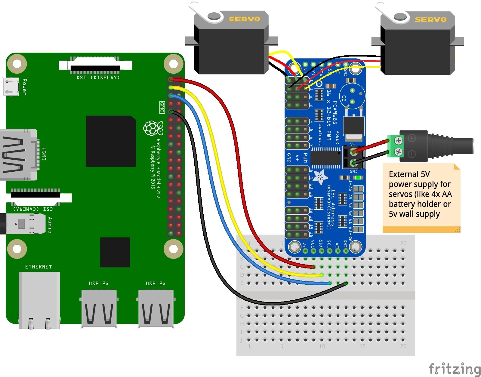
Interfacing PSoC 4S & Servo & Raspberry PiThe GPIO pins are defined as follows on the Raspberry Pi 3B+.
The SG90 can be wired to any of the available PWN ports in the 16-channel servo driver. Connect the servo motors as shown below.
By adjusting the frequency on the PWM pins, the SG90S will turn as instructed by pulse widths.
Install the following packages to run this project
sudo apt-get install python-smbus
sudo apt-get install i2c-tools
Test the i2c ports using the command. If an Adafruit PWM breakout is properly connected and it's set to it's default address -- meaning none of the 6 address solder jumpers at the top of the board have been soldered shut -- it should show up at 0x40 (binary 1000000) as follows:
sudo i2cdetect -y 1Install Adafruit's ServoKit Library and pynout lib
sudo pip3 install adafruit-circuitpython-servokit
pip install pynputAssemble the servo motors to a 3D-printed servo mount.
Mount the Pi camera to the case, and then to the servo mount. Next, connect the flex cable to the camera module where copper fingers should be facing the camera. Connect the CSI Cable to the Raspberry Pi as shown.
- Type in the following command to take a still picture and save it to the Desktop:
raspistill -o Desktop/image.jpgOne of the most common uses of servo motor control is to rotate the field of view of a camera. Many security cameras employ servos in both the horizontal and vertical planes. Servo1 is used to pan the camera from left to right, while Servo2 is used to pan the camera from top to bottom.
# 0 to 180 deg as 2% - 12% PWM
pwm = GPIO.PWM(servo_pinX,50) # 50Hz - 20ms PWM period
pwm2 = GPIO.PWM(servo_pinY,50) # 50Hz - 20ms PWM period
pwm.start(7) # start PWM by rotating x axis to 90 degrees
pwm2.start(2) # start PWM by rotating y axis to 90 degrees

for ii in range(0,1):
    pwm.ChangeDutyCycle(2.0) # rotate to 0 degrees
    time.sleep(1)
    pwm.ChangeDutyCycle(12.0) # rotate to 0 degrees
    time.sleep(1)
    pwm.ChangeDutyCycle(7.0) # rotate to 0 degrees
    time.sleep(1)
    pwm2.ChangeDutyCycle(2.0) # rotate to 0 degrees
    time.sleep(1)
    pwm2.ChangeDutyCycle(7.0) # rotate to 0 degrees
    time.sleep(1)
    pwm2.ChangeDutyCycle(2.0) # rotate to 0 degrees
    time.sleep(1)
Run the Capsense_camera_controller.py to change the camera's position using the PSoC 4 trackpad.
Working 🔭Connect the micro-USB cable to the kit and the other end to the Raspberry Pi. Use the controller as a trackpad to move the camera positions.
The Final Setup is shown here.
----------------------------------------------------------------------------------------------------------------
If you faced any issues in building this project, feel free to ask me. Kindly suggest new projects that you want me to do next.
Give a thumbs up if it really helped you and do follow my channel for interesting projects. :)
Share this video if you like.
Github - https://github.com/Rahul24-06
Happy to have you subscribed: https://www.youtube.com/c/rahulkhanna24june?sub_confirmation=1
Thanks for reading


Comments
Please log in or sign up to comment.