


Hardware components | ||||||
_ztBMuBhMHo.jpg?auto=compress%2Cformat&w=48&h=48&fit=fill&bg=ffffff) |
| × | 1 | |||
 |
| × | 1 | |||
 |
| × | 2 | |||
 |
| × | 1 | |||
 |
| × | 1 | |||
Software apps and online services | ||||||
 |
| |||||
The project aims to construct a small prototype of how PIR sensor integrated with Arduino, can help to build a security system for home environment. The motive was to know if there is any intruder at the main gate of the house. With the relay system, an AC 220v alarm system can also be integrated which can make tone/noise if the sensor detects any presence.
we are going to mount the system on the door panel and use it as a human presence detector.
First, realize that everything — humans, animals, even inanimate objects — emit a certain amount of IR radiation. How much IR radiation they emit relates to the body or object’s warmth and material makeup. Humans can’t see IR, but we’ve designed electronic detection devices to pick up these signals. PIR sensors are that kind of device.
Passive infrared (PIR) sensors use a pair of pyroelectric sensors to detect heat energy in the surrounding environment. These two sensors sit beside each other, and when the signal differential between the two sensors changes, the sensor will engage. IR radiation focuses on each of the two pyroelectric sensors using a series of lenses constructed as the sensor’s housing. These lenses widen the device’s sensing area.
As we are interested to mount the security device on the door or gate, we need to minimize the field of view of the sensor. That's why masking was used.
Power cables of the device is connected to 220v AC. The device is bridged with a transformer 12-0-12 to make 12volt DC from AC. Later the 12volt DC is converted into 5volt by a 7805 voltage regulator. For switching high voltage alarm system, a SPDT-Relay was used with 2A current specification. After programming and implementing the whole circuit at breadboard, a bare-bone Veroboard with the ATMega328p-Arduino chip and all other components are soldered onto it.
Schematic diagram of the circuitUsed an old battery case to set all the components together. Little bit of glue andfragments of plastic to surround the upper layer, makes itsome kind of waterproof :-p.
- At first the system goes to initialization state, remains idle for 10 seconds.
- Then, whenever the sensor detects human presence it remains in active status for 1.350 seconds indicated by RED led.
- When the system is on active status, it rings alarm indicated by piezo buzzer.
- Relay is used for high voltage AC switching. Now relay is integrated with piezo buzzer.
- After being active for 1.350 seconds, it goes to idle state for 10 seconds.
- while it is on idle state, the sensor ignores all event it detects.
Before you use Relay, you must know magnetic components like: Relay, are harmful for this kind of sensitive circuits. That's why always use Transistors for switching circuit to control Relay component. Here, I didn't use Transistor on schematic diagram to make it less complicated. But at final implementation, I have used transistor switching circuit to control relay. There are many switching circuits on the web, try to search and find the best and suitable for you :).
Happy Making!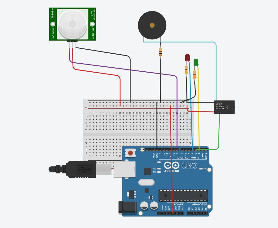


Comments
Please log in or sign up to comment.