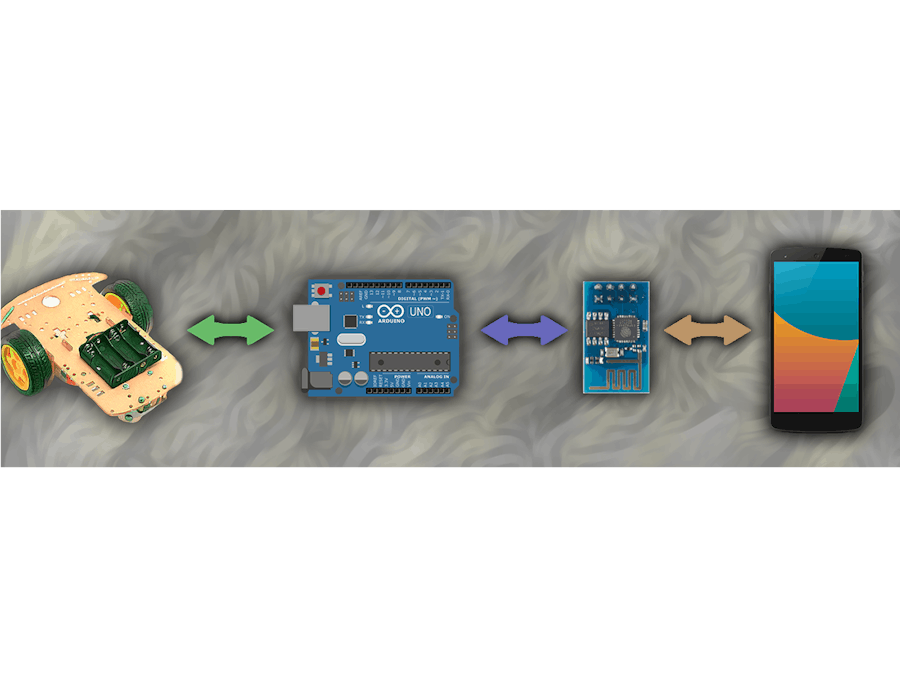
This project guide to make Wi-Fi controlled robot with simple functionalities. Follow steps and make your own robot as you wish. So you can extend your own project by learning this basics (e.g., home automation system). If you want to download PDF file of this post click on button below.
Required Components
First start with motor connection, then connect motor driver to Arduino. After that, configure Arduino and ESP8266. It’s pretty easy and go through following steps.
Step 1L298 Motor Driver module can handle two motors. OUT1, OUT2 control one motor and OUT3, OUT4 control another motor(there is no order for this. turning direction is decide IN pins). So power supply is simple, as Figure-01. +12v pin is commonly use with GND, for power up module. Also you can use +5v pin to give 5v to module and take out 5v from module. When using 12v battery and Arduino together, you can use +12v pin to connect with battery and +5v pin to give power to Arduino. That is the advantage of this +5v pin. There are four IN pins for control turning direction. As a example, by giving +5v to IN1 pin and 0v(GND) to other three pins, the motor rotate which is connected to OUT1 and OUT2. If you give +5v to both IN1 and IN2 it doesn’t work, because motor try to rotate both direction. Therefore carefully handle IN pins and identify what are the turning directions handled by IN pins.
Step 2The wiring diagram showing in Figure-02. You can make it without any effort. So, if you want you can use this
for check it.Step 3This module is use to connect with Android device and communicate with Arduino. For more details about ESP8266 module
. The program for ESP8266 is depend on programming plan. I use client server architecture for implement this system. The Android device is the server of this system and ESP8266, Arduino both are client. So, ESP8266 can program by using Arduino IDE and the program code can be differ according to the functionalities. I use few simple functions such as speed control, turning, bi-direction. However, you can use this to program ESP8266.Step 4The connection is very simple as shown in Figure-03. I use only one connection among ESP8266 and Arduino. And ESP8266 send server data to Arduino through in that connection (ESP8266 Tx –> Arduino Rx (Pin 10)). So the connection is serial connection. Next program Arduino, for read serial data which are coming from ESP8266. Here is
for Arduino.Make sure ESP8266 Vcc connect to 3.3V on Arduino.
Step 5In this scenario Android device behave as a server. Deploy local server by using portable Wi-Fi hotspot in Android device. Here is
for Android device. If you want you can edit code as preference. So, there is .apk file as well.Those are the main steps, so the summary is shown below. More details about code is included in each sample code.
ReviewESP8266 module – ESP8266, Sample Code for ESP8266
Arduino – Figure-03, Sample Code for Arduino
Android device – Install android app
That’s all. Feel free to ask any question, regarding to this project.
Thank you!
Rajitha Kumara


_ztBMuBhMHo.jpg?auto=compress%2Cformat&w=48&h=48&fit=fill&bg=ffffff)


Comments
Please log in or sign up to comment.