


Hardware components | ||||||
_ztBMuBhMHo.jpg?auto=compress%2Cformat&w=48&h=48&fit=fill&bg=ffffff) |
| × | 1 | |||
 |
| × | 1 | |||
 |
| × | 1 | |||
 |
| × | 1 | |||
 |
| × | 1 | |||
 |
| × | 1 | |||
 |
| × | 3 | |||
 |
| × | 1 | |||
 |
| × | 1 | |||
Software apps and online services | ||||||
 |
| |||||
ABOUT THIS PROJECT
Materials:- Arduino Uno R3
- Standard Jumper Wires
- 3 LED lights (I used Red, Green, and Blue but you can use whatever colors you want)
- 3 220 ohm resistors
- HC-SR04 Sonar
- Breadboard
Step1 | Setting up the LEDs
Open up Arduino IDE and open a new sketch by going to File>New. Let's get the LEDs working first. Go ahead and delete the default
void
So that you get a clear screen.
Now we need to define our pins the red pin is connected to pin 3. The green pin is connected to pin 4. And the blue pin is connected to pin 5. So lets make 3 contsint with values as 3, 4, and 5.
const int redPin = 3;const int greenPin = 4;const int bluePin = 5;
Now we need to set these pins as INPUT in the function pinMode(). pinMode() takes in two values. First a int value for which pin we want control. Second a state (either OUTPUT or INPUT normally) value. And since we only need to do this once we put it in the void setup() function.
NOTE: Sometimes the state value ofpinMode()will not beINPUTorOUTPUTbut that is a topic for a different tutorial.
void setup(){ pinMode(redPin, OUTPUT); pinMode(greenPin, OUTPUT); pinMode(bluePin, OUTPUT);}
Now we need to set our colors up. My favorite way of doing this is to set each color in a void[nameofcolor]() then call it when needed in the loop() function. To set up our voids we need to understand how to turn on LEDs in the Arduino IDE. The easiest way of doing this is to use the analogWrite() function. analogWrite() takes in two ints values. First the pin that you want to affect. This can be a number or the name of a int, or it can be the exact pin key that the component is connected to. For example, if we wanted to use the red LED we could say
//EXAMPLE SCRIPT | DO NOT CODE INTO SKETCHanalogWrite(redPin); // This method uses the int name analogWrite(3); // This method uses the exact pin key
analogWrite(); also takes in a second int. This int is for the brightness of the LED. This number can range anywhere between 0 and 255 with 0 being completely off and 255 being completely on. For example.
//EXAMPLE SCRIPT | DO NOT CODE INTO SKETCHanalogWrite(redPin, 0); // redPin is completely offanalogWrite(redPin, 127); // redPin is about halfway onanalogWrite(redPin, 255); //redPin is completely on
Armed with this information we can now code our color functions.
void Red(int VAL){ analogWrite(redPin, VAL); analogWrite(greenPin, 0); analogWrite(bluePin, 0);}void Green(int VAL){ analogWrite(redPin, 0); analogWrite(greenPin, VAL); analogWrite(bluePin, 0);}void Blue(int VAL){ analogWrite(redPin, 0); analogWrite(greenPin, 0); analogWrite(bluePin, VAL);}
On every void we take in a intVAL so that we can customize how bright we want the LED to be when we call it in the voidloop() function. For example.
//EXAMPLE SCRIPT | DO NOT CODE INTO SKETCHvoid loop(){ Red(255); // Red is set to completely on Green(127); // Green is set to about halfway on Blue(0); // Blue is set to off }
Now let's test each LED to make sure there working. In between the voidsetup() and the color functions write a voidloop() function. voidloop() executes the code inside it then loops to the beginning of the function and does it all over again. voidloop() is were all the "Moving pieces" of your code goes. In the voidloop() function set all of the LEDs to completely on.
void loop(){ Red(255); Green(255); Blue(255);}
By now your script should look like this:
const int redPin = 3;const int greenPin = 4;const int bluePin = 5;void setup(){ pinMode(redPin, OUTPUT); pinMode(greenPin, OUTPUT); pinMode(bluePin, OUTPUT);}void loop(){ Red(255); Green(255); Blue(255);}void Red(int VAL){ analogWrite(redPin, VAL); analogWrite(greenPin, 0); analogWrite(bluePin, 0);}void Green(int VAL){ analogWrite(redPin, 0); analogWrite(greenPin, VAL); analogWrite(bluePin, 0);}void Blue(int VAL){ analogWrite(redPin, 0); analogWrite(greenPin, 0); analogWrite(bluePin, VAL);}
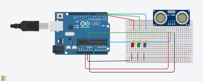
All three LEDs should now light up. If not check fig1 and make sure your wiring is correct. Then check for errors in your code. If all else fails see the Questions or Comments at the bottom of the tutorial.
If all LEDs light up. Congratulations! You have completed step one of the tutorial. Move on the Step 2
Step2
Now that we have the LED lights working we need to turn our attention to the HC-SR04 sonar sensor. But first, if you haven't already, let's turn off the LEDs by removing the color functions form the voidloop() like this.
void
The HC-SR04 works by sending out a sonic burst when it receives a pulse for 10 microseconds. Then once it receives a sonic burst it sets the echo pin to HIGH for the duration of the incoming pulse.
Lastminuteengineers has a very good animation on how this works.
Source: https://lastminuteengineers.com/arduino-sr04-ultrasonic-sensor-tutorial/#:~:text=Connecting%20the%20HC-SR04%20to%20the%20Arduino%20is%20pretty,that%20looks%20similar%20to%20the%20illustration%20shown%20below.
Because we now how fast sound travels in air (which is 340 m/s) and since physics teaches us that Distance = Speed / Time. When we convert 340 m/s to cm/µS(microsecond) which equals 0.034 cm/µs. Plug all of our numbers into an equation and divide our answer by 2 (because our little sonic burst has to hit the object then return to the sensor). We can find the distance of the object in cm. This information we can use in our project to do some pretty cool things.
First at the top of our sketch we need to set our pins for echo and trigger.
const int echoPin = 9;const int trigPin = 8;
We also need to make another int to keep track of our distance. Do not set this as const because this value will change. To stay organized put this in-between the pin int and the void setup()
int distance;
NOTE: Do not setintdistanceto equal anything yet. We will do that later.
Next we need to set echoPin as INPUT and trigPin as OUTPUT inside of voidsetup()
void setup(){ pinMode(redPin, OUTPUT); /* pinMode(greenPin, OUTPUT); This code should already be here pinMode(bluePin, OUTPUT); */ pinMode(echoPin, INPUT); // Add this line pinMode(trigPin, OUTPUT); // Add this line}
Now we need to code the sonic burst. To save space I'm going to call it a ping from now on. So first we set trigPin to LOW then to HIGH for 10 µs then back to LOW. To stay organized lets do that in a void. How do you set a pin to LOW or HIGH? I'm glad you asked. First we need to understand what LOW and HIGH even mean. LOW and HIGH are constant values. When a pin is set as OUTPUT in the pinMode(), LOW means that a pin is at 0V. (on 5V boards). HIGH means that a pin is at 5V. To set a pin as LOW or HIGH we use the digitalWrite(); function digitalWrite(); takes in two values. First it takes in a int value as the pin key. Just like analogWrite(); this value can either be in the form of physical number (like 3 for example) or as a int name (like redPin for example). The second value it takes in is a state value (normally LOW or HIGH). Now that we know how to do it, let's code the ping in a void function that we'll call sendPing();
void sendPing(){ digitalWrite(trigPin, LOW); delayMicroseconds(5); digitalWrite(trigPin, HIGH); delayMicroseconds(10); digitalWrite(trigPin, LOW);}
Now in the void loop() we need to call the sendPing() function then we need to figure out how long echoPin reads HIGH. This is easy with the function pulseIn(); which takes a pin key (either as a number or int name) and a state (either HIGH or LOW) then it reads how long said pin key was HIGH or LOW, then returns the value as a int in µs. So let's make a new int and call it duration. duration will be our Time value in the equation above. Now we can set distance to equal to duration x 0.034/2. Code it like this.
void loop(){ sendPing(); int duration = pulseIn(echoPin, HIGH); distance = 0.034 * duration / 2;}
Now that we have our distance in cm. We need some means of displaying the int distance. We can do this by using the Serial.begin(); function in the void setup() function. Serial.begin(); allows our board to be able to talk to the computer via the COM4 Window.
NOTE: Your COM4 might have a different number on the end based on which board and/or usb port you plug your board into. For example on my second Arduino board, it is not the COM4 window but the COM5 window. Both windows use the same button to open.
To open the COM4 window, click the Serial Monitor button on the top righthand side of the Arduino IDE window.
We need set Serial.begin(); to 9600 to retrieve usable information. So in the void setup() function we will do just that.
void setup(){ pinMode(redPin, OUTPUT); /* pinMode(greenPin, OUTPUT) pinMode(bluePin, OUTPUT); This code should already be here pinMode(echoPin, INPUT); pinMode(trigPin, OUTPUT); */ Serial.begin(9600); // Add this line}
Now we need to distance out on the screen
To do that let's create a function we'll call this printToScreen();. We'll say that printToScreen(); takes in a int that we'll call TARGET then print it to the screen using the print(); and the println(); functions. By now you can probably guess how this works. print(); and println(); takes in one input this can either be a float, int, or booleen. Then it prints the input on the Serial Monitor. But there's only one little problem. Some materials (such as cloth and skin) can cause the HC-SR04 to get a bit mixed up and report negative numbers. Also the sonar looses accuracy around 50cm so we need to clamp the sonar to be within these numbers. To do this is very easy. We are going to create a new function and call it clamp();. clamp(); will take in 3 inputs, a int VAL, a int min, and a int max. Then we'll set up a string of if() statements to clamp the values. Write your code like this.
int clamp(int VAL, int min, int max){ if(VAL <= min){ VAL = min; return VAL; } else if(VAL >= max){ VAL = max; return VAL; } else{ return VAL; }}
Put this function underneath all of the other voids in the sketch to maintain neatness.
Next we'll clamp distance by saying at the bottom of void loop()
distance=clamp(distance,0,50);
Now it's finally time to print distance to the Serial Monitor. Using information from the above segment we code void printToScreen(); like this.
void printToScreen(int TARGET){ Serial.print(TARGET); Serial.println(" cm");}
Also make sure to call in printToScreen(); at the bottom of void loop() and set its' TARGET to distance like this
void loop(){sendPing(); /*int duration = pulseIn(echoPin, HIGH); This code should already bedistance = 0.034 * duration / 2; heredistance = clamp(distance, 0, 50); */printToScreen(distance); // Add this line}
Now upload the project to your board, grab a cm ruler and check to see if it is working. If not check fig1 and make sure your wiring is correct. Then check for errors in your code. If all else fails see the Questions or Comments at the bottom of the tutorial.
NOTE: The HC-SR04 sensor most likely will be off by a couple of cm. You can figure out by how much by running a couple of test. Then to fix it add or subtract your number fromTARGETinSerial.print(TARGET);this step isn't necessary for the project to work as a whole
const int redPin = 3;const int greenPin = 4;const int bluePin = 5;const int echoPin = 9;const int trigPin = 8;int distance;void setup(){pinMode(redPin, OUTPUT);pinMode(greenPin, OUTPUT);pinMode(bluePin, OUTPUT); pinMode(echoPin, INPUT); pinMode(trigPin, OUTPUT); Serial.begin(9600); }void loop(){sendPing();int duration = pulseIn(echoPin, HIGH);distance = 0.034 * duration / 2;distance = clamp(distance, 0, 50);printToScreen(distance); }void Red(int VAL){analogWrite(redPin, VAL);analogWrite(greenPin, 0);analogWrite(bluePin, 0);}void Green(int VAL){analogWrite(redPin, 0);analogWrite(greenPin, VAL);analogWrite(bluePin, 0);}void Blue(int VAL){analogWrite(redPin, 0);analogWrite(greenPin, 0);analogWrite(bluePin, VAL);}void sendPing(){digitalWrite(trigPin, LOW);delayMicroseconds(5);digitalWrite(trigPin, HIGH);delayMicroseconds(10);digitalWrite(trigPin, LOW);}int clamp(int VAL, int min, int max){ if(VAL <= min){ VAL = min; return VAL; } else if(VAL >= max){ VAL = max; return VAL; } else{ return VAL; }}void printToScreen(int TARGET){ Serial.print(TARGET); Serial.println(" cm");}
If everything works. Congratulations! You have completed step two move on to step three.
Step3
Now it is finally time to take all of our information we have gathered and make it do something! This is actually the simple part of project. All we have to do is write a string of if() statements at the bottom of void loop().
First we need to decide at what distances which light we want to show.
Here are my choices;
- Red @ distances btw 33 - 50 cm
- Green @ distances btw 16 - 32 cm
- Blue @ distances btw 1 - 15 cm
Now we write our if() statement at the bottom of void loop()
void loop(){sendPing(); /*int duration = pulseIn(echoPin, HIGH);distance = 0.034 * duration / 2; This code should already be heredistance = clamp(distance, 0, 50);printToScreen(distance); */if(distance >= 0 && distance <= 15){ Blue(255); Green(0); Red(0); }else if(distance >= 16 && distance < 33){ Add these lines of code Green(255); Blue(0); Red(0); } else if (distance >= 33 && distance <= 50){ Red(255); Green(0); Blue(0); } */}
NOTE: You do not HAVE TO addGreen(0);,Blue(0);,etc.for theif()statement to work. I have it in there so that --- in the case that I want multiple light to light up within a said range --- I can do so by editing the null values.
Now upload the sketch to the board. And watch your project run. If it doesn't work as intended check fig1 and make sure your wiring is correct. Then check for errors in your code. If all else fails see the Questions or Comments at the bottom of the tutorial.
Congratulations! You have completed the tutorial.

Comments
Please log in or sign up to comment.