

Hardware components | ||||||
 |
| × | 1 | |||
| × | 1 | ||||
Software apps and online services | ||||||
 |
| |||||
 |
| |||||
| ||||||
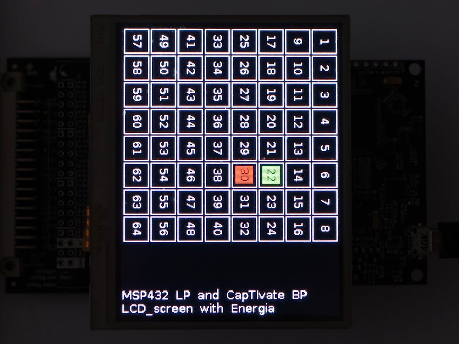
This project uses the CapTIvate MCU Development Kit as a BoosterPack and displays the pads on the Kentec 3.5" SPI screen.
The idea is to design a generic capacitive board I could use with different projects, like a board with 8 x 8 pads for a calculator.
This project shows an example of a programmable sensor.
Step 0: Hardware and SoftwareHardware includes (external links)
- and optionally a custom capacitive board.
Software is available on Windows, Linux and macOS (external links)
To turn the board with the MSP430FR2633 MCU into a BoosterPack, we are going to use the holes the board provisions for the extended 40-pin BoosterPack.
However, the MSP430FR2633 board only uses 20 pins, so we solder those 20 pins only.
The CapTIvate board rises an interrupt on pin 8 and sends the messages in bulk, through either the UART port (pins 3 and 4) or the I²C port (pins 9 and 10).
This project uses the I²C port, so we remove the jumpers for UART, TXD/P1.4 and RXD/P1.5.
This frees the UART port on the LaunchPad (pins 3 and 4) for the serial console.
We're going to use CapTIvate Design Center GUI, available for Windows, Linux and macOS, to
- Design the capacitive board
- Configure the MSP430FR2633
- Generate the code
Configuring a capacitive board is very easy thanks to the automatic options, one for assigning the I/O and another for generating the code.
Let's work with CapTIvate Design Center GUI:
- Open the CapTIvate Design Center GUI
- Call the menu File > Project New to create a new project, name it,
- Drag and drop a controller and a button group from the tool bar to the working space
- Double click on the button group to open the Button Sensor Properties window
- Set Element group to 64
- Close the Button Sensor Properties window
- Double click on the controller to open the Controller Properties window,
- Select MSP430FR2633 IRHB as Device
- Click on Auto-Assign or assign the Unconnected electrodes to the Sensors BTN00 manually
- Check the OK label is green
- Click on Generate Code Source
- Close the Controller Properties window
- Call the menu File > Project Save to save the project
Referring to the schematics helps and improves the assignation of the elements to the TX and RX ports.
Let's work with Code Composer Studio:
- Open Code Composer Studio
- Call the menu Project > Import CCS Project and select the project generated previously
- Click on the hammer icon or call the menu Project > Build Project to build the project
- Prepare the hardware by assembling the different boards together, from left to right:
- the capacitive board
- the CapTIvate BoosterPack
- the programmer board
- Then connect the programmer board to the USB port of the computer
Back to Code Composer Studio,
- Click on the bug icon or call the menu Run > Debug to upload the program to the MSP430FR2633 and launch the debugger.
- Click on the red square to end the session.
To check every works fine,
- Return to CapTIvate Design Center GUI
- Call the menu Communication > Connect
- Move one finger on the capacitive board
The screen shows the pads with proximity in orange and the pads with touch in green.
I'm using the MSP432 LaunchPad using Energia 1.6.10E18. Energia is based on the Arduino / Wiring framework.
The project calls three libraries:
- the Wire library for the I²C protocol to communicate with the CapTIvate BoossterPack,
- the SPI library for the SPI protocol to communicate with the Kentec screen BoosterPack,
- the Screen_K35_SPI library for the Kentec 3.5" SPI screen is bundled with Energia.
One single function getCapTIvate64() acquires and processes the data from the BoosterPack.
The function isSomething() returns true if there is at least one pad with proximity or touch.
There are five kinds of messages called packets but our project only uses the Cycle Packet, which eases reading and decoding.Remember, the capacitive board has been configured with 1 sensor, 16 cycles of 4 elements each, for a grand total of 64 pads.
A message includes
- one preliminary byte with the length of the message,
- byte 0 is the Command Byte, always 0 for Cycle Packet,
- byte 1 is the Sensor ID Byte, always 0 in the project,
- byte 2 is the Cycle ID Byte, 0~15 in the project,
- bytes 3 to 5 are the Cycle State Bytes with, the first 12 bits (MSB) for proximity and the last 12 bits (LSB) for touch, one bit per element of the cycle.
- the remaining bytes of the message (except the last 2) are the Element LTA and Element Count Bytes, 4 bytes by element and 4 elements, with details (long term average and count) for each element of the cycle,
- the last two bytes of the message for the 16-bit checksum (CRC).
Texas Instruments provides all the information needed with the Technology Guide.
A logic analyser was very helpful for decoding the I²C messages! pan>
The two functions prepareScreen() and refreshScreen() manage the screen. To speed up display, only modified areas are updated.
The screen is refreshed only
- after the 16 cycles have been completed, and
- if there are pads with proximity and pads with touch.
The screen shows the pads with proximity in orange and the pads with touch in green.
Let's work with Energia!
- Open Energia,
- Call the menu File > Open and select the sketch CapTIvate_64.ino,
- Click on the check icon or call the menu Sketch > Verify/Compile to compile the sketch,
- Prepare the hardware by assembling the different boards together, from bottom to top:
- the CapTIvate BoosterPack connected to the capacitive board,
- the MSP432 LaunchPad,
- the Kentec 3.5" SPI screen.
- Then connect the MSP432 LaunchPad to the USB port of the computer.
Back to Energia,
- Click on the arrow icon or call the menu Project > Upload to upload the binary to the MSP432 LaunchPad.
- Move one finger on the capacitive board.
Multiple areas are displayed on the screen as CapTIvate tracks multi-touch.
The screen shows the pads with proximity in orange and the pads with touch in green.
Optionally, you can use Code Composer Studio instead of Energia.
- Open Code Composer Studio,
- Call the menu Project > Import Energia Project and select the sketch CapTIvate_64.ino,
- Proceed as previously, build and upload.
On the picture below, I put my left hand on the capacitive board: the board detected 8 pads with touch and 7 pads with proximity.
The CapTIvate is very efficient in sorting signal from noise, and touch from proximity.


Comments
Please log in or sign up to comment.