Through the practical development of the radar system for detection of objects at short distances, material is shown for connecting the digital development electronic board Arduino Mega 2560 (programmed with integrated development environment Arduino IDE) with a personal computer that uses a program made with Processing software that allows computer to display the view of a particular object that is detected by the radar system for detection of objects at short distances.
The practical development of the radar system for detection of objects at short distances will also show the way of practical connection of all necessary digital electronic components and their programming in order to show the importance of the use of the scientific field of digital electronics and programming in education. process in various other scientific fields and disciplines.
Additionally, MS windows software "Processing" was used to receive the data from the Arduino and to draw the radar image on the personal computer.
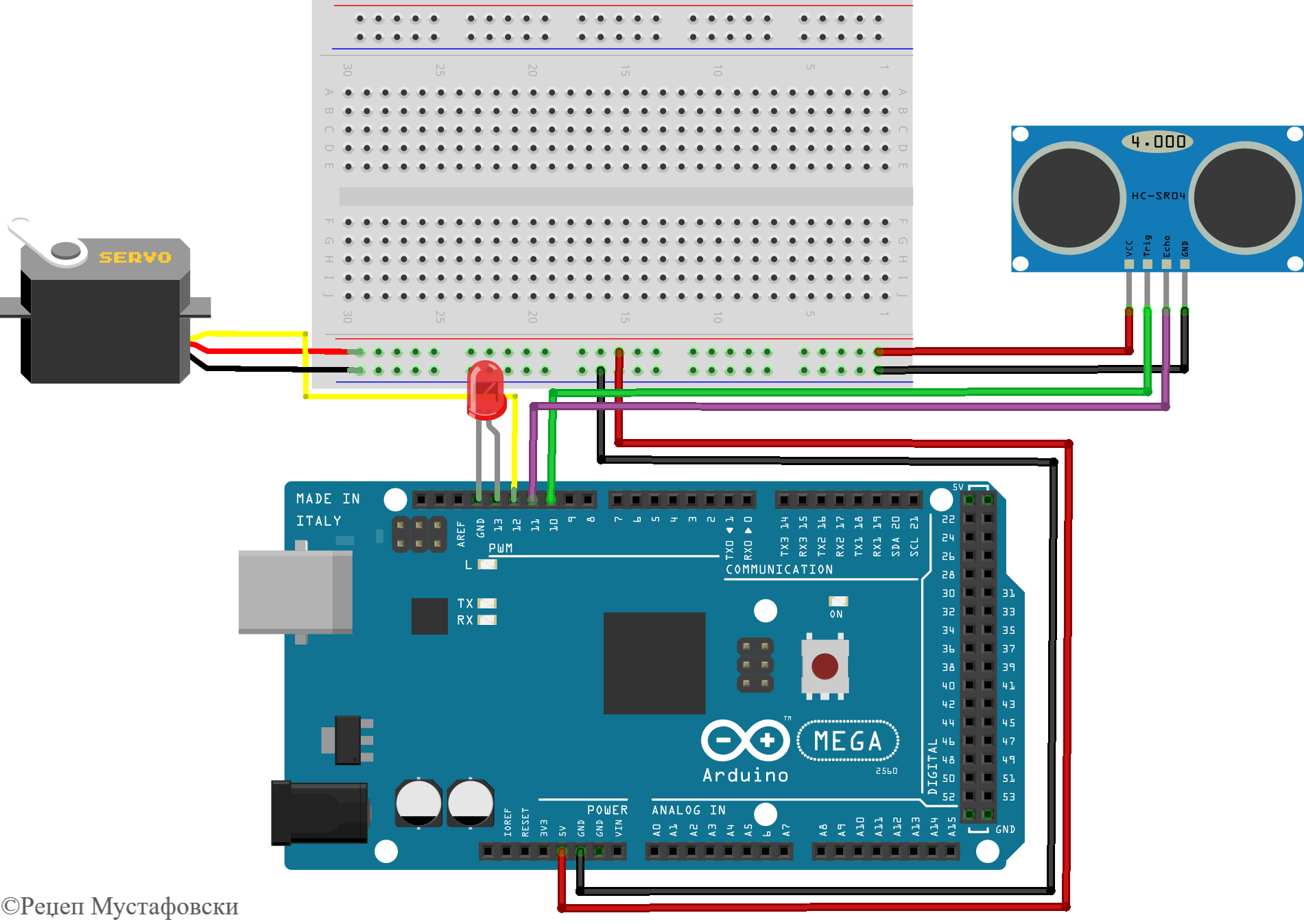
The block diagram of the connection is given below.
The Arduino IDE software enables the programming of the Arduino Mega 2560, along with all the necessary components, such as the Arduino Mega 2560 board, the HC-SR04 ultrasonic sensor, the servo motor, the protoboard, the connecting wires and the ultrasonic sensor holder that allows the connection all components to each other and the construction of the radar system for detection of objects at short distances. A personal computer program developed in the processing development environment, on the other hand, made it possible to read data coming from the Arduino Mega 2560. Communication and data reading is provided via a USB cable connection. After receiving the information, the PC program creates a drawing of the valuesgiven by the ultrasonic sensor HC-SR04. It is important for the mutual communication in the PDE to first enter a library for defining the way of communication from the field "Sketch", the field "Import Library→ Serial", shown below in the picture.
To provide serial communication, a serial port must be defined, commonly called myport, which allows us to communicate serially with the port on our computer. It is also necessary to define a variable for the current information to reach the program itself smoothly. In the integrated development environment we have setup () and loop () functions, and in the processing development environment we have setup () and draw () functions, it is noticeable that here we have draw (), instead of a loop () function. In order to establish the serial connection, i.e. setup () in the processing development environment, we need to select the port to which the Arduino Mega 2560 is connected and download the necessary data. With Serial.begin (9600) in the integrated development environment, and value (9600) in the processing development environment, where the two development environments are enabled to communicate with each other.
3. Practical appearance and radar connection
Based on everything that has been shown so far, we got some idea of what the radar and its operation would look like. This section will specifically show the appearance of the radar and its function through images.
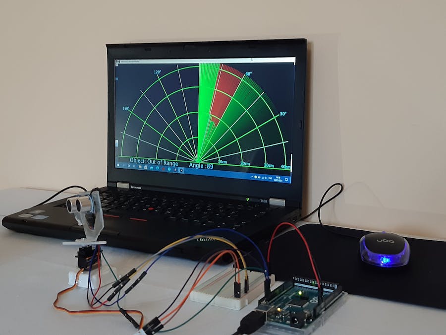
Through this graphic display, the image below, gives a visual representation of what radar looks like in reality. The difference in reality is that the ultrasonic sensor itself is attached to the servo motor. In the picture you can see the connection of wires in different colors, usually the black wire is used to connect the common end or the minus, the red wire is used to connect the positive pole of the power supply, while the other wires can be selected at will. What is important when connecting the other parts and the different wires is the visibility when connecting. Connection visibility makes it easier to check connected elements.
The Processing program developed in the processing development environment plots the radar surface based on the information and displays the detected target, as shown in the figure below.
According to the given image, we can say that the ultrasonic sensor noticed a target at an angle of 123 ° and a distance of 5 cm, so that is why in that area we have a red drawing, which should be a kind of warning of danger. The performed radar system for detection of objects at short distances as part of this master thesis in our laboratory is shown in the previous image above in the project.
You can download the code in the section "Code".The algorithms of the Arduino and Processing code that describe the way the codes work are given below.
1) Open the QuickStego tool to implement image steganography as shown in figure below. Now click on "Open Image" to open an image.
2) To select the cover image as shown in the image below, click on any image that will act as our cover image to implement steganography to hide our confidential data. In our case we will choose the cover image marked as a test image on which text will be hidden.
3) After selecting the cover image, it is loaded into QuickStego as shown in the image below.
4) We can now write our secret message on the cover image displayed on the tool on which the steganography will be performed. This message is written in the black message box on the right side of the cover image. The data or information that will be hidden in the image will be taken from the output of the serial port of the integrated development environment Arduino IDE for the angle and distance of the object detected by the radar system for detection of objects.
5) Click the "Hide text" button to hide the text and save it to the image, otherwise it will not be saved. The text message is then hidden in the image as shown in the image below.
6) Clicking the "Save image" button to save the image allows QuickStego users to select the location where the image in which the data is stored will be saved.
This is the file that when transferred will look like any normal image, but there is actually some secret information hidden inside the image itself.
4.2. Decrypting information
1) Open the QuickStego tool, and then click"Open image" to open the image as shown in the image below.
2) The image below selects the clip or cover image that was received by the sender.
3) The selected cover image is now open in the QuickStego tool which will show the hidden text message in black screen as shown in the image below.
4) In case the text is not displayed, it can be obtained by clicking the "Get text" button to display the hidden text of the cover image as shown in the image below.


_wzec989qrF.jpg?auto=compress%2Cformat&w=48&h=48&fit=fill&bg=ffffff)


Comments
Please log in or sign up to comment.