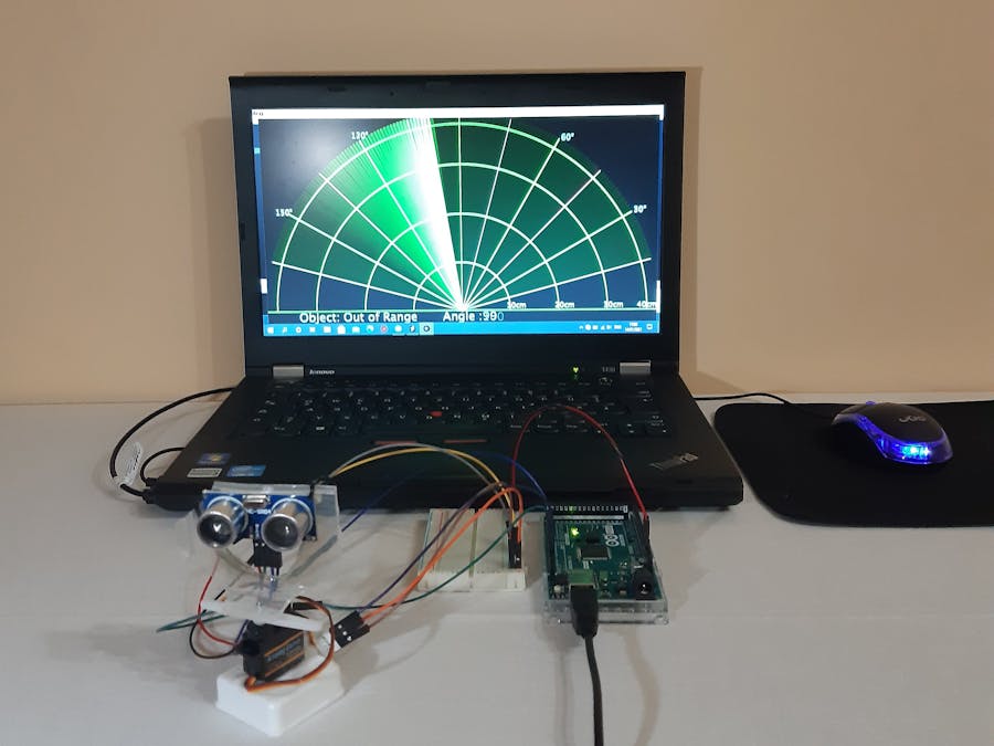
The development of the model have been performed in the Simulink working environment. Simulink is a MATLAB-based graphical programming environment for modeling, simulating and analyzing multi-domain dynamical systems. It has support for Arduino Mega 2560 digital development electronic board. The Simulink model itself is a replacement for the code written in the Arduino IDE integrated development environment.
Additionally, MS windows software "Processing" was used to receive the data from the Arduino and to draw the radar image on the personal computer.
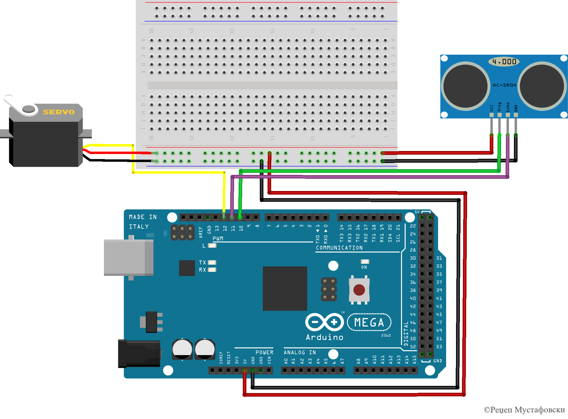
The block diagram of the connection is given below.
To launch the Simulink simulation tool, enter the "simulink" command in the Matlab command window and then select "Blank Model" in the start page of the Simulink simulation tool to create a new blank model.To create a new custom model, select the "Simulink Library Browser" icon, which is located on the toolbar or can be opened via the "View Option" located on the main toolbar, which allows you to select a large number of block tools using which creates a new simulation model that will simulate the radar system for detection of objects at short distances.
The first block is "Sine Wave", which is located in the "Sources" library on the left side of the "Simulink Library Browser" window.
(❶) The “Sine Wave” block tool is used for sinusoidal wave output and can operate in time-based or sample-based mode. After placing the block tool on the desktop by double-clicking on the block tool, the surface of the block parameters opens, on which the parameters and the type of work of the block tool can be set. This signal will generate array of integers which are used to position the angle of the servo motor.
(❷) The "Data Type Conversion" block is necessary to convert the data in integer values which are further send to the servo motor. The parameters are given below.
(❸) The "Standard Servo Write" block is used to set the shaft position of the standard servo motor, which rotates the radar. The standard servo write block is part of the library "Simulink Support Package for Arduino Hardware" in the "Common" section on the left side of the window "Simulink Library Browser”.
The input range can be between 0 and 180 degrees. For 0 input, the standard servo motor shaft is at 0 degrees, while for 180 input the standard servo motor shaft is at 180 degrees. The digital pin number is stated and each block must have a unique pin number within the model. After placing the block, double-clicking on it opens the parameters which are given below.
Beside sending the signal/angle to the servo motor we will send this information to the serial port in order to be received by the personal computer which will draw the radar image. The angle value in order to be send to the serial port first will be converted to string (❹) and after that to ASCII.
(❺) Next we select the block "Ultrasonic Sensor" which is located also in the library "Simulink Support Package for Arduino Hardware" in the section "Sensors" on the left side of the window "Simulink Library Browser".
The “Ultrasonic Sensor” block has built in protocol which triggers the ultrasonic sensor, and calculates the distance from the object. used to measure the distance to an object in meters. This block has one output which is giving the distance from the object in meters. The parameters are given below.
(❻) The block tool "Gain" is used to convert the distance value from the ultrasonic sensor from meters to centimeters. The parameters are given below.
(❼) (❽) (❾) Are combining the data for angle and distance in one string which has structure as is given below.
(❿) The "String to ASCII" block is used to convert the constructed array into ASCII vector which can be further send to the serial port.
(⓫) The "Serial Transmit" block is used to send data to the serial port of the Arduino. It is located in the library "Simulink Support Package for Arduino Hardware" in the section "Common" on the left side of the "Simulink Library Browser" window
(⓬) Can be used to monitor the data during the simulation.
3. Programming and running of the Simulink modelOnce the entire simulation model is ready, a physical connection is made between Arduino Mega 2560, the servo motor and the ultrasonic sensor by using the protoboard. Additionally, the Arduino Mega 2560 is connected to the personal computer using USB cable.
In order to program the Arduino from Matlab and Simulink you should select in the configuration parameters of the model in the part Hardware Implementation you should select The Arduino Mega 2560 Hardware Board as is given below. Previously in the Matlab it is necessary to install the support for Arduino Hardware through the option "Adds on".
Once this is done, the simulation model can be performed by clicking on the graphic button "Build, Deploy & Start" which is located in the toolbar and will be successfully transferred to the Arduino Mega 2560.
4. Radar image drawing on the PC by the Processing softwareThe image of the radar drawn by the program in Processing is given below. You can download the code in the section "Code". This is the algorithm of the processing code that is given below.
According to the given image, we can say that the ultrasonic sensor detected a target at 73 ° and a distance of 8 cm.


_wzec989qrF.jpg?auto=compress%2Cformat&w=48&h=48&fit=fill&bg=ffffff)


Comments
Please log in or sign up to comment.