Hello everyone,
Whenever it comes to any Arduino, everyone needs a power supply to juice up their projects. Some people like me uses ordinary mobile chargers and some likes to use a 9v battery and few go with a LiPo battery. But I have a better way!!! Why don’t we just make our own power supply? Even its cheaper than a traditional mobile charger yet with more flexibility.
Today we are going to make a really small and cheap power supply, which will give output of 5v but by replacing only few components we can get 12 or 9v easily.
Components Needed- Four diodes
- Two capacitors
- One transformer
- One led
- One resistance
- One 7805 ic
(If we just change the transformer and the 7805 IC to 7812, we can get an output of 12v.)
Circuit DesigningLet’s learn how to make a linear power supply step by step. First of all, let’s clear our aim. So, the main purpose of a power supply is to change 220v AC to 5v DC.
It will include 4 steps-
Step 1
Stepping down 220v AC to 9v AC. We will use a transformer for this purpose. Transformer have 2 coils which are in mutual induction with each other. The number of coils in both the coils decide the output voltage. The simple formula is-
Vin / Vout = Np/ Ns
The transformer we are using here will give us an output of 9v AC.
Step 2
Rectifying the AC using Diode. Now we will use a bridge rectifier which consist of 4 diodes in following configuration. It will rectify AC to a rippled DC. Rippled DC is not a perfect DC.
You can see the diagrams for input and output waves.
Step 3
Now we have to filter it. For filtration we are going to use capacitor. Capacitors allow AC to flow through them and Block DC to pass through them. So, we will use a capacitor in shunt with our circuit.Input and output signals can be seen in wave diagrams.
Step 4
Last step is regulation. For this we will use a 7805-voltage regulator IC. 7805 will give a constant output of 5v. If we use a 7812 IC, we will get a constant 12v output. For a 12v Power Supply we will need to change the transformer to a 12v AC and change regulator to 7812 IC.
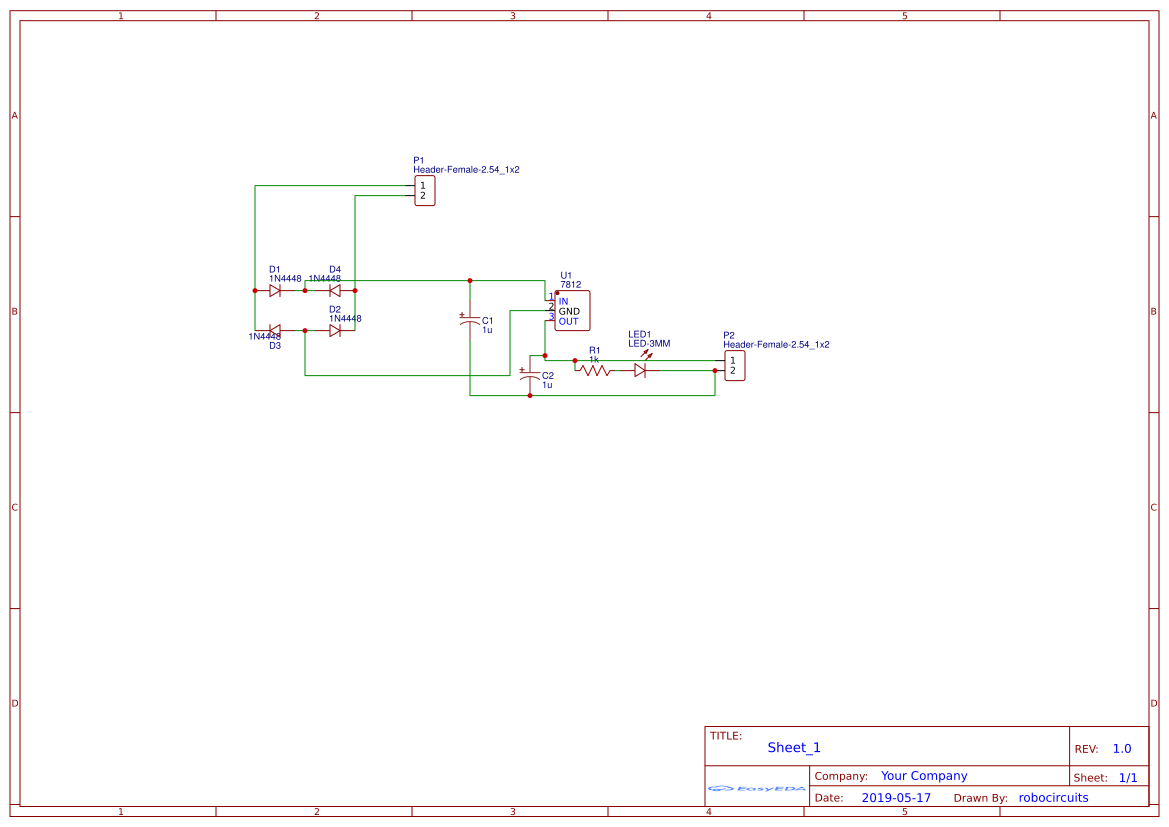
Circuit DiagramLet’s draw a circuit diagram for the same. So here is the circuit diagram for our project.
Then I went to easyeda.com, made the same schematics using the components given in its library.
Then I made a PCB design for it. The PCB layout looks cool. I also added a.png logo for my channel.Next, I get my gerber files using the button given in task bar and downloaded my gerber files.
Gerber_Linear-Power-SupplyDownload
Then I went to jlcpcb.com to order my PCBs, I uploaded my files on the order page.
When I was checking the colors, I found a new Matte Black option. I thought I should give it a try.
Then I click on add to cart and then clicked on checkout. I selected my address shipping method and paid it using PayPal.
I got them after 8 days. Actually, I ordered matte black as well as green for a little comparison. Matte black color looks awesome. It has a great texture and also for your knowledge it takes 2 extra days for this color.
Here is a little comparison between black and matte black.
Then I soldered all the components on the board. And also screwed the transformer on the board.I added an extra wire with a plug.
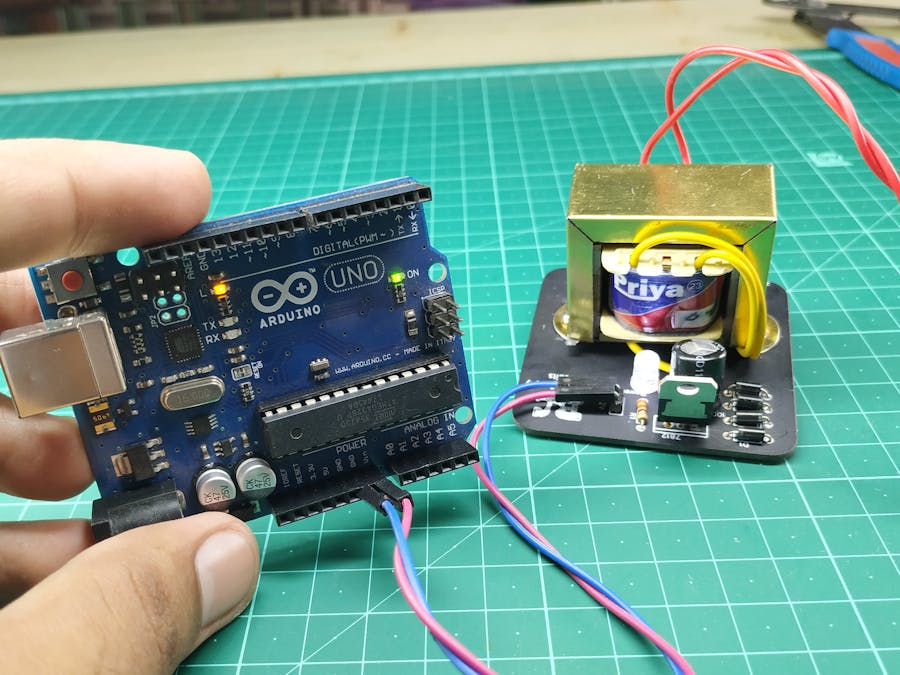
TestingThen I plugged it in AC socket and the LED starts glowing. I tested it with Arduino Nano and Arduino UNO as well, both worked completely fine.
This linear power supply is really cheap and looks awesome. The matte black PCB gives it a decent look. So, what you think of it??? Is it cool? Let me know in the comment section. If you dislike this video hit the dislike button and if you liked it you what you have to do. If you are new to this channel Subscribe Click Here. Thank you for Reading have a nice day.
Social LinksFacebook – https://fb.com/robocircuitsInstagram – https://instagram.com/robocircuitsTwitter – https://twitter.com/robocircuitsInstructables – https://www.instructables.com/member/PrashantS161/Arduino – https://create.arduino.cc/projecthub/robocircuits


Comments
Please log in or sign up to comment.