Water Level Switch is a simple electronic project made by using basic electronic components like LED, resistors, transistors. The transistor is one of the most versatile active electronics components on the planet. Almost every IC is build using transistors. Without transistors, almost every electronics appliance we use today won’t be possible. We are going to see how to make a small water level switch using a single D882 transistor. You can see the pinout of the D882 transistor in the given image.
We can use this circuit as a simple water tank level indicator. Or we can make several of these circuits and build a tank level indicator with several levels. This circuit can be customized in any way you like.
Basic Components :
Let’s see what components are required for this.
2. UTSOURCE LED
4. Circuit wire
Tools Required:
1. Soldering Iron
2. Iron Stand
3. Flux
4. Nose pliers
Circuit Diagram:
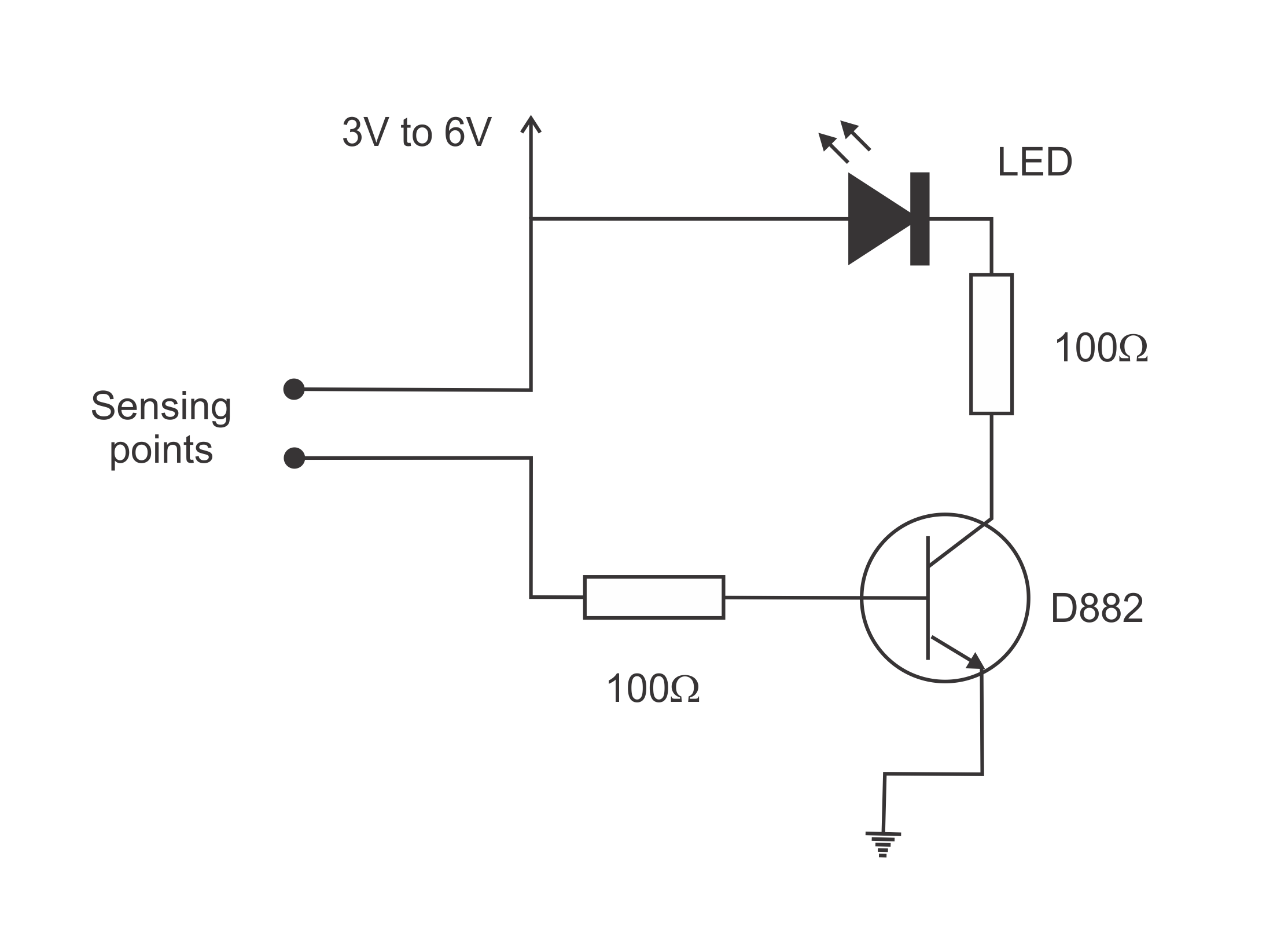
This is the basic circuit diagram of our water level indicator circuit. LED is connected in series with a 100Ω resistor and then it is connected to the collector of D882 transistor. You can observe the positive pin of the LED is connected to the positive supply. The base of the D882 transistor is connected to the water sensing wire through a 100Ω resistor. Both these resistors are there to limit the current flowing through the led and the base pin of the D882 transistor as well. If the current is not limited both the LED and the D882 transistor can be damaged. The emitter pin of the D882 transistor is connected to the ground pin of the power supply.
Procedure:
Step 1: Arrange the components
Step 2: Solder ground wire to the emitter of the D882 transistor
Step 3: Solder the 100Ω resistor to the collector pin of the D882 transistor. Solder the negative pin of the LED to the remaining pin of the 100Ω resistor.
Step 4: Solder the 100Ω resistor to the base pin of the D882 transistor.
Step 5: Solder two sensing wires and the positive power wire to their respective places.
Step 6: Now power the circuit. Led should be turned on when the water is touched in both sensing wires.
How It Works:
As you can see, one of the sensing wires is directly connected with the positive supply. Other sensing wire is connected to the base pin of the D882 transistor through a resistor. When the water is touched in both sensing wires
Conclusion:
This circuit can be used to indicate an overflow of a water tank. Or a water level of a water tank. You can integrate this with other circuits and fully automate the pump systems. You can visit here. if you need other transistors, IC chips, LED, Capacitors to make the projects you want.
Follow us for more projects or follow us on social media
Instagram - https://instagram.com/robocircuits
Facebook - https://facebook.com/robocircuits
YouTube - https://youtube.com/robocircuits


Comments
Please log in or sign up to comment.