In this very COVID-19 affected world now it has become difficult to move around places either for work or to shop some groceries or even for a small get-together for family and friends. The very sole reason for this problem is no vaccine is found yet. But still to carry on day to day task at meeting we can we can sanitize it with some device like UV- light we have an ability to kill extremely dangers viruses.In this very COVID-19 affected world now it has become difficult to move around places either for work or to shop some groceries or even for a small get-together for family and friends. The very sole reason for this problem is no vaccine is found yet. But still to carry on day to day task at meeting we can we can sanitize it with some device like UV- light we have an ability to kill extremely dangers viruses.
This UV Rover has an extreme ability to go into corners of small office rooms to disinfect the place using its UV rays spreading into each corner, walls, and under the table. The utmost priority is given to protecting the people from this kind of viruses.
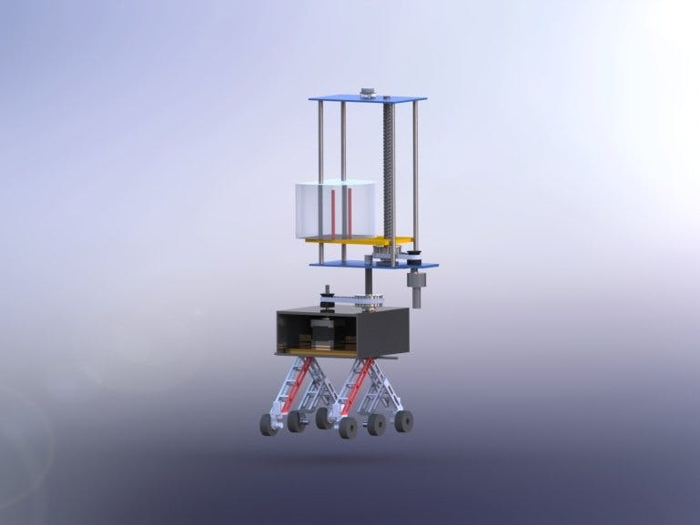
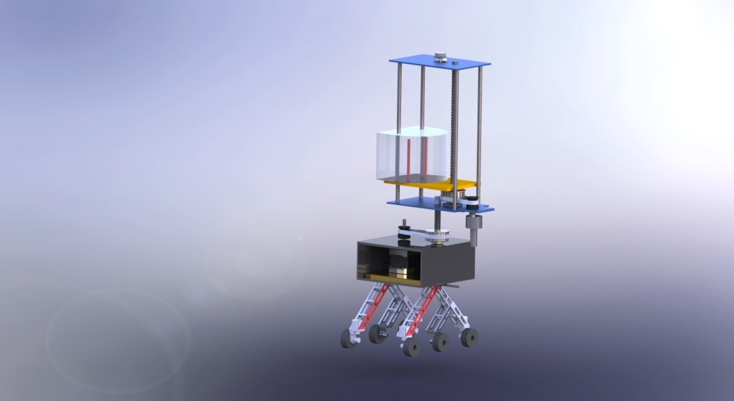
This has a simple working mechanism placed on a rover with six wheels for mobility. A lead screw mechanism for vertical motion of UV light, LiDAR sensor and ultrasonic sensor for mapping and obstacle detection respectively, along with a battery pack for power supply. All these are centrally controlled by NVIDIA Jetson Nano controller which brings the best out of each sensor.
The PlanAs of now, more than 22.9M cases have been reported globally, resulting in more than 7, 99, 000 deaths and still…So need to replace the human being in annihilating the virus by our robot/s as much as possible. The robot has the capability to detect the most touching thing in the environment like a door handle, chair, table, bed, etc and disinfect it very precisely and also reach to each and every area of the room (smallest to largest). The robot can safeguard any living thing in the surrounding area at any time by immediate switching off the system
Mechanical DesignDesign consists of two main components
1) Rover-Rocker Bogie mechanism
2) Lead Screw Mechanism
Rover has six wheels, each with its own individual motor. The two front and two rear wheels also have individual steering motors. This steering capability allows the vehicle to turn in place, a full 360 degrees. The four-wheel steering also allows the rover to swerve and curve, making arcing turns. Rocker, one each on the left and right side of the rover. Connects the front wheel to the differential and the bogie in the rear. Bogie, Connects the middle and rear wheels to the rocker. Rocker bogie mechanism also provides maximum stability. Aluminium T6 grade is selected as material for structural members of the rover because of its very good strength to weight ratio and good machinability characteristics. Direction of the robot is controlled via software commands given to motors through the controllers and distribution boards.
Steering Mechanism:
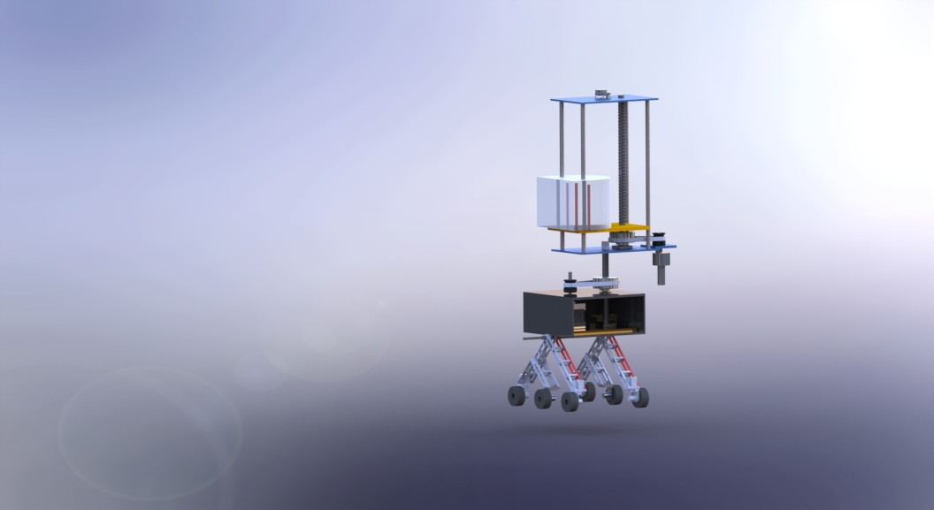
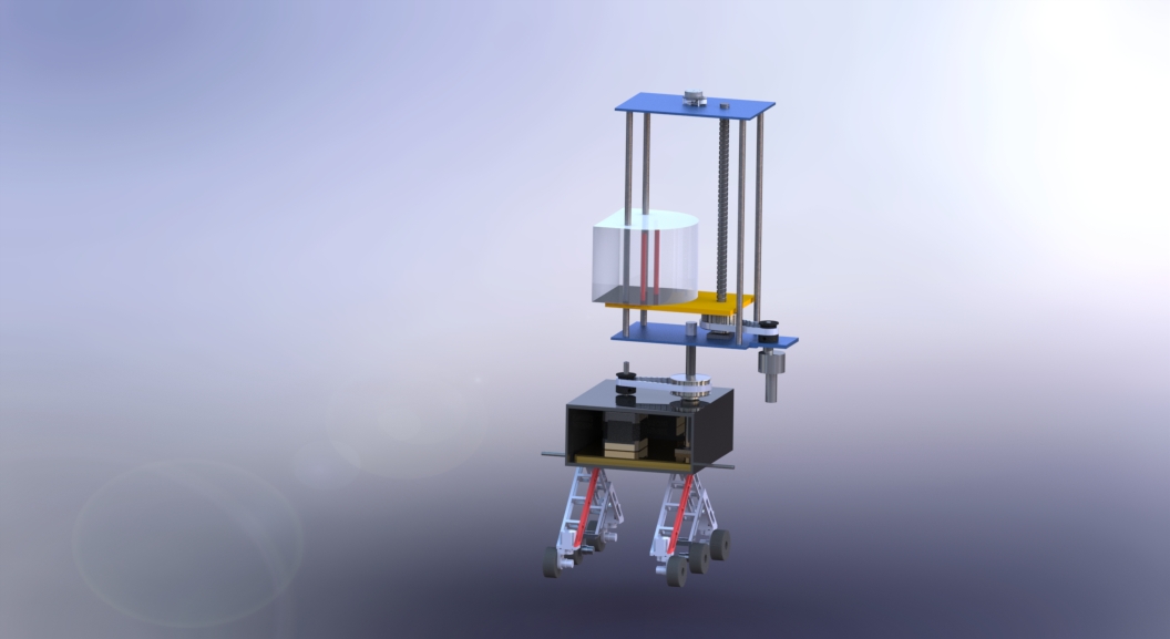
All Six wheels are powered by Johnson DC Motors for forward and backward movements. Moreover, two front wheels and two rear wheels are having one more DoF provided with a NEMA 23 stepper motor for steering and on-spot rotating purpose. As a result, the front and rear wheels will rotate about vertical axis. The arrangement of the same is shown in the figure (2, 3).
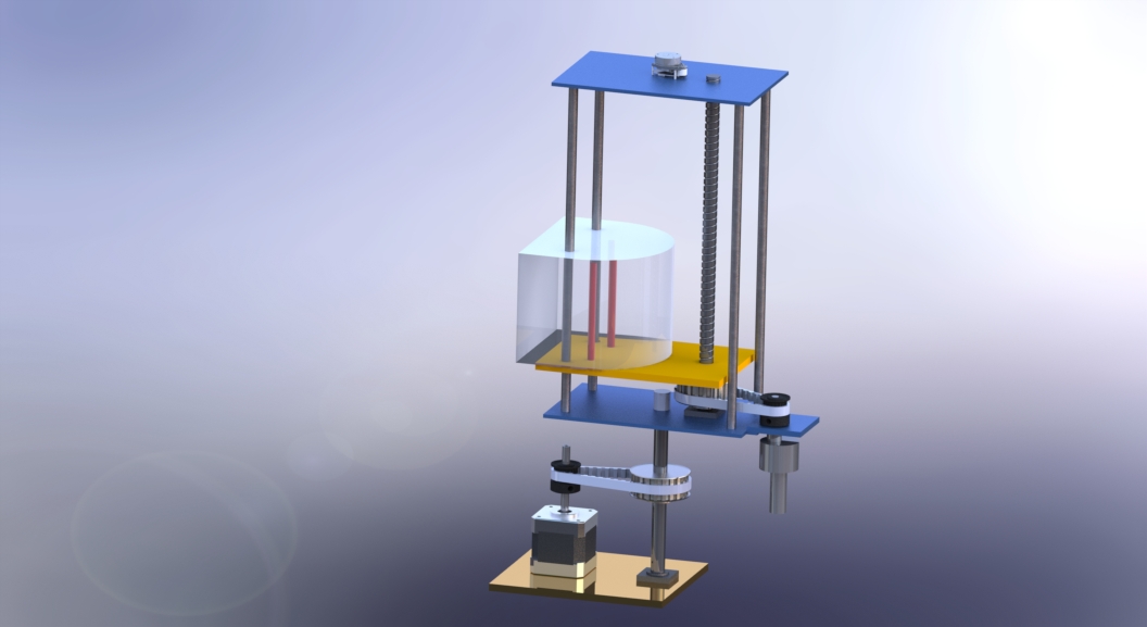
There are different types of mechanism available like hydraulic, pneumatic as well as mechanical. But considering the objective of this project mechanical serves the purpose the most effectively giving it an edge over hydraulic and pneumatic. Here we have used a lead screw placed vertically which is attached to a DC geared motor via a belt drive. The lead screw here provides many mechanical advantages like having a self-locking mechanism which will help in case of power failure in rover and stop sudden fall of support plate to strike hard on bottom plate resulting in UV-light failure, other than this there are many advantages of lead screw like low maintenance cost and less wear of components of repetitive usage.
The timing belt has many mechanical advantages over other like chain drive or V-belt drive which provides the following advantages:
Minimal vibration, Reduced noise
Positive slip proof engagement
Virtually no elongation (stretching) due to wear
High mechanical efficiency
Power transmission efficiency is not lost with use
Weight savings
The lead screw is placed at the centre of bottom and top plate. There are in total three supports attached for holding and stability and one should serve the purpose of guide which is necessary to constrain the rotation of the top plate. As the UV plate move linearly up and down continuously it will remove the material at solid surface gradually. So, it is better to use wear resistive material for guide. Wear resistive material has good advantages like longer life at a given cost, lower noise level, reduced driving power consumption and more uniform wear on rods. The material selected for guide is phosphorus bronze UV light housing with reflector is placed on plate shown in fig. Reflector used here is of porex virtek reflective ptfe. This reflector Maximize lighting efficacy – With over 97% average reflectance from 220nm to 400nm, less light is lost to absorption. It also Eliminate hot and cold spots –scatters light in all directions, spreading UV light evenly across a surface and eliminating cold spots where bacteria may survive
As the lead screw rotates, the support plate moves up and down depending on the side of rotation. Now this mechanism can only sanitize one side and to provide 360-degree rotation the whole rover must rotate about its vertical axis standing at that place, and using this met h od will cause more battery drain as we must supply power to all wheels. So, to simplify this problem we have placed our lead screw housing on thrust body which is attached with a servo motor. Now as we provide motion to servo motor the whole housing rotates and thus, we can get whole 360-degree rotation of UV-light.
The rover is an autonomous device which has capability to act according to the situations. These capabilities are achieved by attaching different kind of sensors to the rover. Centrally the rover is controlled by Jetson Nano which is a compact and a powerful controller. Starting from area detection we have used LiDAR sensor which is placed high up on the top of upper plate of lead screw which detects 360 degree around the area, after that whole data is feed to the controller and it starts moving. Once the data is acquired and rover moves, then obstacles are detected using ultrasonic sensors, after detection of obstacle rover changes its path at the same time the path followed by rover is also recorded so that it can follow that path again for further use.
Now the most important process is sanitization which is done by UV-light. Why UV-light? The reason lies behind the fact that UV has shorter wavelength and consist higher energy which is capable enough to kill harmful bacteria’s and germs It is highly effective at decontamination because it destroys the molecular bonds that hold together the DNA of viruses and bacteria, including "superbugs, " which have developed a stronger resistance to antibiotics. Using UV-light for sanitation has been clinically approved for home and office purposes.
Since the rover has smaller footprint as a result it can reach smaller and compact spaces to sanitize the area. Due to the use of powerful sensors the motion and detection becomes more precise. The sensors used can also detect the most frequently touched objects in its vicinity which makes it easier to determine where and how much amount of time is required to sanitize a particular area. The interesting part is it also sanitizes the path it traces so that no germs or bacteria attached to the wheels of rover can spread. This is rover is built using standard parts which a readily available in market for easy replacement and maintenance.
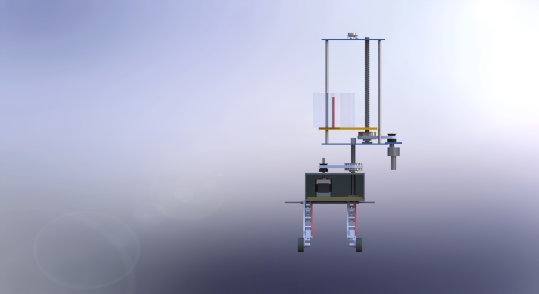
As the overall dimension of the system shown in figure 6 which ensure the reachability of the system to each and every corner of the room and also it can fit through standard bathroom stall door
Required HardwareThe required components are already listed above. But we will have a look at them again with their photographs. The components are:
Jetson Nano Development Kit. NVIDIA® Jetson Nano™ Developer Kit is a small, powerful computer that lets you run multiple neural networks in parallel for applications like image classification, object detection, segmentation, and speech processing. All in an easy-to-use platform that runs in as little as 5 watts.
Technical Specifications:
GPU 128-core Maxwell
CPU Quad-core ARM A57 @ 1.43 GHz
Memory 4 GB 64-bit LPDDR4 25.6 GB/s
Storage microSD (not included)
Video Encode 4K @ 30 | 4x 1080p @ 30 | 9x 720p @ 30 (H.264/H.265)
Video Decode 4K @ 60 | 2x 4K @ 30 | 8x 1080p @ 30 | 18x 720p @ 30 (H.264/H.265)
Camera 2x MIPI CSI-2 DPHY lanes
Connectivity Gigabit Ethernet, M.2 Key E
Display HDMI and display port
USB 4x USB 3.0, USB 2.0 Micro-B
Others GPIO, I2C, I2S, SPI, UART
Mechanical 69 mm x 45 mm, 260-pin edge connector
SlamTec RP-LIDAR A1: RPLIDAR A1 is a low cost 360 degree 2D laser scanner (LIDAR) solution developed by SLAMTEC. The system can perform 360 degree scan within 6meter range. The produced 2D point cloud data can be used in mapping, localization and object/environment modelling.
RPLIDAR A1’s scanning frequency reached 5.5 hz when sampling 360 points each round. And it can be configured up to 10 hz maximum. RPLIDAR A1 is basically a laser triangulation measurement system. It can work excellent in all kinds of indoor environment and outdoor environment without sunlight.
Technical Specifications:
Dimensions: 70 x 98.5 x 60 (mm)
Distance Range: 0.5 to 12 meters
Angular Range: 0-360 degrees
Distance Resolution: <0.5mm (<1% of the actual distance)
Angular Resolution: >1 degree
Sample Duration: 0.5ms
Sample Frequency: Max 8000Hz (Typically greater than 4000Hz)
Scan Rate: 5-10 Hz (Typical value is 5.5)
Li-Po battery to power the Rover
lithium polymer battery, or more correctly lithium-ion polymer battery (abbreviated as LiPo, LIP, Li-poly, lithium-poly and others), is a rechargeable battery of lithium-ion technology using a polymer electrolyte instead of a liquid electrolyte. High conductivity semisolid (gel) polymers form this electrolyte. These batteries provide higher specific energy than other lithium battery types and are used in applications where weight is a critical feature, like mobile devices and radio-controlled aircraft.[1]
We will use LiPo or Lithium Polymer Batteries for our rover. The initial proposal is to use 2 batteries to power the whole rover, each of a rating of 13V and a battery capacity of more than 5000mah.
Ultrasonic Sensors for obstacle avoidance
An ultrasonic sensor is an electronic device that measures the distance of a target object by emitting ultrasonic sound waves, and converts the reflected sound into an electrical signal. Ultrasonic waves travel faster than the speed of audible sound (i.e. the sound that humans can hear). Ultrasonic sensors have two main components: the transmitter (which emits the sound using piezoelectric crystals) and the receiver (which encounters the sound after it has travelled to and from the target).
In order to calculate the distance between the sensor and the object, the sensor measures the time it takes between the emission of the sound by the transmitter to its contact with the receiver. The formula for this calculation is D = ½ T x C (where D is the distance, T is the time, and C is the speed of sound ~ 343 meters/second).
For our rover, we will use a number of these sensors which will continuously collect data and based on that data, we will detect any obstacles that are present around the rover and take the necessary actions like stopping the rover or changing the direction of the rover.
HC-SR04 Sensor FeaturesOperating voltage: +5V
Theoretical Measuring Distance: 2cm to 450cm
Practical Measuring Distance: 2cm to 80cm
Accuracy: 3mm
Measuring angle covered: <15°
Operating Current: <15mA
Operating Frequency: 40Hz
Motor Drivers to control the motors
Two motor drivers are used here for two different motor's one stepper motor driver and another brushed dc motor driver for stepper and brushed dc motor respectively.
Specification for brushed dc motor driverLength 67.00mm
Breadth 43mm
Height 15mm
Weight 120.00gram
Specification for stepper motor driverLength 82.00mm
Breadth 50mm
Height 30mm
Weight 24.00gram
Arduino Mega as the slave MicrocontrollerThe Arduino Mega 2560 is a microcontroller board based on the ATmega2560. It has 54 digital input/output pins (of which 15 can be used as PWM outputs), 16 analog inputs, 4 UARTs (hardware serial ports), a 16 MHz crystal oscillator, a USB connection, a power jack, an ICSP header, and a reset button. It contains everything needed to support the microcontroller; simply connect it to a computer with a USB cable or power it with an AC-to-DC adapter or battery to get started.
In our rover, the Mega will be connected as a slave to the Jetson Nano. It will run a minimal version of ROS, will be connected with all the sensors and motors due to the large number of IO pins it has, the IMU, Ultrasonic sensors, GPS sensor and the Motor drivers. It will collect the sensor data and constantly publish it on the relevant programmed ROS topics so that Jetson Nano can make the decisions based on this data and instruct the Mega to control the Motors accordingly.
Now, we will look at the technical specifications of the Arduino Mega in detail using the table below.
Technical Specifications:Microcontroller ATmega2560
Operating Voltage 5V
Input Voltage (recommended) 7-12V
Input Voltage (limit) 6-20V
Digital I/O Pins 54 (of which 15 provide PWM output)
Analog Input Pins 16
DC Current per I/O Pin 20 mA
DC Current for 3.3V Pin 50 mA
Flash Memory 256 KB of which 8 KB used by bootloader
SRAM 8 KB
EEPROM 4 KB
Clock Speed 16 MHz
LED_BUILTIN 13
Length 101.52 mm
Width 53.3 mm
Weight 37 g
IMU Sensor for Direction detection
An inertial measurement unit (IMU) is an electronic device that measures and reports a body's specific force, angular rate, and sometimes the orientation of the body, using a combination of accelerometers, gyroscopes, and sometimes magnetometers. IMUs are typically used to maneuver aircraft (an attitude and heading reference system), including unmanned aerial vehicles (UAVs), among many others, and spacecraft, including satellites and landers. Recent developments allow for the production of IMU-enabled GPS devices. An IMU allows a GPS receiver to work when GPS-signals are unavailable, such as in tunnels, inside buildings, or when electronic interference is present.[1] A wireless IMU is known as a WIMU.
We use the IMU in our project to figure out the direction in which I rover will be moving. This is a necessity for autonomous navigation which our rover supports.
GPS Module to get the current location of the robot
We use the GPS sensor to add navigation feature in our bot. We want to create a system in which we just have to provide the destination coordinates to the bot and the rover will do the rest of the work, that is figuring out the path from its current location to the destination, obstacle avoidance and the sense of direction it is moving in.
This is only possible if the rover has a GPS sensor on board so that it can sense the distance between its current location at any given instant to the destination and also detect when it reaches the destination, which is an indication to stop.
MotorsTwo different types of motors are used for two purposes of vertical motion as well as rotational motion. Brushed dc motor is used for providing the vertical motion whereas stepper motor is used for providing the rotational motion.
Specification for brushed dc motorLength 62.00mm
Breadth 37(Gbox)mm
Height 27(motor)mm
Weight 177.00gram
Specification for stepper motorLength 51mm
Breadth 57mm
Height 57mm
Weight 650.00gram
costing for mechanical componentsNow comes the interesting and a rather tedious task, the software part of the project! This setup is divided into several parts, so let us get started.
i) OS Setup on the NanoFirst things first, when we get the Nano out of the box, we need to install an Operating System. Just follow the tutorial linked below.
Getting Started with Jetson Nano
ii) Install ROS on the NanoThis is the tricky part. There are a number of tutorials on ROS installation in Linux, but most of them are outdated so, I had to spend quite a lot of time to figure this one out.
Some important things to note:
Firstly, most tutorials cover the installation of ROS Kinetic, but it is outdated and hence you can not directly install it using pip install. So, we will have to go with the ROS Melodic Full Desktop Version.
So, just follow this tutorial below but replace kinetic with Melodic.
ROS Installation on Jetson Nano
If everything goes all right, you would be able to see the catkin_ws folder has 3 sub folders and you can successfully compile using catkin_make command in this.
Moreover, you can run the command "roscore" in the terminal to start ROS service.
iii) Setup software to run our CarNow, we will have to install all the dependencies required to run the car. For this, we will use a popular open source project, the "Donkey Car" project, which will be ported to the Jetson Nano. So, just follow the below tutorial to setup this:
1. Install Dependenciesssh into your vehicle. Use the the terminal for Ubuntu or Mac. Putty for windows.
sudo apt-get update
sudo apt-get upgrade
sudo apt-get install build-essential python3 python3-dev python3-pip libhdf5-serial-dev hdf5-tools nano ntp
Optionally, you can install RPi.GPIO clone for Jetson Nano from here. This is not required for default setup, but can be useful if using LED or other GPIO driven devices.
2. Setup Virtual Envpip3 install virtualenv
python3 -m virtualenv -p python3 env --system-site-packages
echo "source env/bin/activate" >> ~/.bashrc
source ~/.bashrcTo install Open CV on the Jetson Nano, you need to build it from source. Building OpenCV from source is going to take some time, so buckle up. If you get stuck, here is another great resource which will help you compile OpenCV.
Note: In some cases Python OpenCV may already be installed in your disc image. If the file exists, you can optionally copy it to your environment rather than build from source. Nvidia has said they will drop support for this, so longer term we will probably be building it. If this works:
mkdir ~/mycar cp /usr/lib/python3.6/dist-packages/cv2.cpython-36m-aarch64-linux-gnu.so ~/mycar/ cd ~/mycar python -c "import cv2"
Then you have a working version and can skip this portion of the guide. However, following the swapfile portion of this guide has made performance more predictable and solves memory thrashing.
Note: In some cases Python OpenCV may already be installed in your disc image. If the file exists, you can optionally copy it to your environment rather than build from source. Nvidia has said they will drop support for this, so longer term we will probably be building it. If this works:mkdir ~/mycar cp /usr/lib/python3.6/dist-packages/cv2.cpython-36m-aarch64-linux-gnu.so ~/mycar/ cd ~/mycar python -c "import cv2"
Then you have a working version and can skip this portion of the guide. However, following the swapfile portion of this guide has made performance more predictable and solves memory thrashing.
The first step in building OpenCV is to define swap space on the Jetson Nano. The Jetson Nano has 4GB of RAM. This is not sufficient to build OpenCV from source. Therefore we need to define swap space on the Nano to prevent memory thrashing.
# Allocates 4G of additional swap space at /var/swapfile
sudo fallocate -l 4G /var/swapfile
# Permissions
sudo chmod 600 /var/swapfile
# Make swap space
sudo mkswap /var/swapfile
# Turn on swap
sudo swapon /var/swapfile
# Automount swap space on reboot
sudo bash -c 'echo "/var/swapfile swap swap defaults 0 0" >> /etc/fstab'
# Reboot
sudo reboot
Now you should have enough swap space to build OpenCV. Let's setup the Jetson Nano with the pre-requisites to build OpenCV.
# Update
sudo apt-get update
sudo apt-get upgrade
# Pre-requisites
sudo apt-get install build-essential cmake unzip pkg-config
sudo apt-get install libjpeg-dev libpng-dev libtiff-dev
sudo apt-get install libavcodec-dev libavformat-dev libswscale-dev libv4l-dev
sudo apt-get install libxvidcore-dev libx264-dev
sudo apt-get install libgtk-3-dev
sudo apt-get install libatlas-base-dev gfortran
sudo apt-get install python3-dev
Now you should have all the pre-requisites you need. So, lets go ahead and download the source code for OpenCV.
# Create a directory for opencv
mkdir -p projects/cv2
cd projects/cv2
# Download sources
wget -O opencv.zip https://github.com/opencv/opencv/archive/4.1.0.zip
wget -O opencv_contrib.zip https://github.com/opencv/opencv_contrib/archive/4.1.0.zip
# Unzip
unzip opencv.zip
unzip opencv_contrib.zip
# Rename
mv opencv-4.1.0 opencv
mv opencv_contrib-4.1.0 opencv_contrib
Let's get our virtual environment (env) ready for OpenCV.
# Install Numpy
pip install numpy==1.16.4
Now let's setup CMake correctly so it generates the correct OpenCV bindings for our virtual environment.
# Create a build directory
cd projects/cv2/opencv
mkdir build
cd build
# Setup CMake
cmake -D CMAKE_BUILD_TYPE=RELEASE \
-D CMAKE_INSTALL_PREFIX=/usr/local \
-D INSTALL_PYTHON_EXAMPLES=ON \
-D INSTALL_C_EXAMPLES=OFF \
-D OPENCV_ENABLE_NONFREE=ON \
# Contrib path
-D OPENCV_EXTRA_MODULES_PATH=~/projects/cv2/opencv_contrib/modules \
# Your virtual environment's Python executable
# You need to specify the result of echo $(which python)
-D PYTHON_EXECUTABLE=~/env/bin/python \
-D BUILD_EXAMPLES=ON ../opencv
The cmake command should show a summary of the configuration. Make sure that the Interpreter is set to the Python executable associated to your virtualenv. Note: there are several paths in the CMake setup, make sure they match where you downloaded and saved the OpenCV source.
To compile the code from the build folder, issue the following command.
make -j2This will take a while. Go grab a coffee, or watch a movie. Once the compilation is complete, you are almost done. Only a few more steps to go.
# Install OpenCV
sudo make install
sudo ldconfig
The final step is to correctly link the built OpenCV native library to your virtualenv.
The native library should now be installed in a location that looks like /usr/local/lib/python3.6/site-packages/cv2/python-3.6/cv2.cpython-36m-xxx-linux-gnu.so.
# Go to the folder where OpenCV's native library is built
cd /usr/local/lib/python3.6/site-packages/cv2/python-3.6
# Rename
mv cv2.cpython-36m-xxx-linux-gnu.so cv2.so
# Go to your virtual environments site-packages folder
cd ~/env/lib/python3.6/site-packages/
# Symlink the native library
ln -s /usr/local/lib/python3.6/site-packages/cv2/python-3.6/cv2.so cv2.so
Congratulations! You are now done compiling OpenCV from source.
A quick check to see if you did everything correctly is
ls -alYou should see something that looks like
total 48
drwxr-xr-x 10 user user 4096 Jun 16 13:03 .
drwxr-xr-x  5 user user 4096 Jun 16 07:46 ..
lrwxrwxrwx  1 user user   60 Jun 16 13:03 cv2.so -> /usr/local/lib/python3.6/site-packages/cv2/python-3.6/cv2.so
-rw-r--r--  1 user user  126 Jun 16 07:46 easy_install.py
drwxr-xr-x  5 user user 4096 Jun 16 07:47 pip
drwxr-xr-x  2 user user 4096 Jun 16 07:47 pip-19.1.1.dist-info
drwxr-xr-x  5 user user 4096 Jun 16 07:46 pkg_resources
drwxr-xr-x  2 user user 4096 Jun 16 07:46 __pycache__
drwxr-xr-x  6 user user 4096 Jun 16 07:46 setuptools
drwxr-xr-x  2 user user 4096 Jun 16 07:46 setuptools-41.0.1.dist-info
drwxr-xr-x  4 user user 4096 Jun 16 07:47 wheel
drwxr-xr-x  2 user user 4096 Jun 16 07:47 wheel-0.33.4.dist-info
To test the OpenCV installation, run python and do the following
import cv2
# Should print 4.1.0
print(cv2.__version__)Now that everything else is done, the only setup that is left is for our Lidar Sensor. First, lets know a little more about the device that we are using:
About RPLIDAR
RPLIDAR is a low cost 2D LIDAR solution developed by RoboPeak Team, SlamTec company. It can scan 360° environment within 6meter radius. The output of RPLIDAR is very suitable to build map, do slam, or build 3D model.
You can know more information aboud rplidar from SlamTec HomePage(http://www.slamtec.com/en).
You can know more information aboud rplidar from SlamTec HomePage(http://www.slamtec.com/en).
How to build rplidar ros packageClone this project to your catkin's workspace src folder
Clone this project to your catkin's workspace src folder
Clone this project to your catkin's workspace src folder
Running catkin_make to build rplidarNode and rplidarNodeClient
Running catkin_make to build rplidarNode and rplidarNodeClient
Running catkin_make to build rplidarNode and rplidarNodeClient
How to run rplidar ros packageCheck the authority of rplidar's serial-port :
ls -l /dev |grep ttyUSB
Add the authority of write: (such as /dev/ttyUSB0)
sudo chmod 666 /dev/ttyUSB0
There're two ways to run rplidar ros package
I. Run rplidar node and view in the rvizroslaunch rplidar_ros view_rplidar.launch
You should see rplidar's scan result in the rviz.
II. Run rplidar node and view using test applicationroslaunch rplidar_ros rplidar.launch
rosrun rplidar_ros rplidarNodeClient
You should see rplidar's scan result in the console
How to remap the USB serial port nameMaybe you should change the usb device port mode with the authority of read and write, more than make the port remap to an fixed name. install USB port remap:./scripts/create_udev_rules.sh
Maybe you should change the usb device port mode with the authority of read and write, more than make the port remap to an fixed name. install USB port remap:./scripts/create_udev_rules.sh
check the remap using following command: ls -l /dev | grep ttyUSB
check the remap using following command: ls -l /dev | grep ttyUSB
Once you have change the USB port remap, you can change the launch file about the serial_port value.<param name="serial_port" type="string" value="/dev/rplidar"/>
Once you have change the USB port remap, you can change the launch file about the serial_port value.<param name="serial_port" type="string" value="/dev/rplidar"/>
RPLidar frame must be broadcasted according to picture shown in rplidar-frame.png
How to install rplidar to your robotrplidar rotate with clockwise direction. The first range come from the front ( the tail with the line).
rplidar rotate with clockwise direction. The first range come from the front ( the tail with the line).
Please keep in mind the orientation of the Lidar sensor while installing it onto your robot. Here is what the axes look like:
Now that this is done, just try to run a sample launch file "view_rplidar" and see the scan results of the topic "/scan" in rviz. It will look something like this:
Now, to add slam to our application, there are several available algorithms. But, we choose Hector Slam for our project. So, let us move on:
Hector Slam Setup for Jetson Nano
We cannot use the native github repo for Hector slam is the nano as we did for the rplidar. We need to make some changes in the Hector slam files to get it up and running. First, here are the commands you need to run:
cd catkin_ws/src/
git clone https://github.com/tu-darmstadt-ros-pkg/hector_slam
Now, after it has been cloned, we will need to make the following changes:
In catkin_ws/src/rplidar_hector_slam/hector_slam/hector_mapping/launch/mapping_default.launchreplace the second last line with<node pkg="tf" type="static_transform_publisher" name="base_to_laser_broadcaster" args="0 0 0 0 0 0 base_link laser 100" />the third line with<arg name="base_frame" default="base_link"/>the fourth line with<arg name="odom_frame" default="base_link"/>
In catkin_ws/src/rplidar_hector_slam/hector_slam/hector_slam_launch/launch/tutorial.launchreplace the third line with<param name="/use_sim_time" value="false"/>
Now that this changes are done, we can go ahead and run the following:
cd ..
catkin_make
Now if everything goes as planned, this will be successfully compiled. This means we are ready to run hector slam on our Nano. Follow these steps in order to do so:
Install ROS full desktop version (tested on Kinetic) from: http://wiki.ros.org/kinetic/Installation/Ubuntu
Create a catkin workspace: http://wiki.ros.org/ROS/Tutorials/CreatingPackage
Clone this repository into your catkin workspace
In your catkin workspace run source /devel/setup.bash
Run chmod 666 /dev/ttyUSB0 or the serial path to your lidar
Run roslaunch rplidar_ros rplidar.launch
Run roslaunch hector_slam_launch tutorial.launch
RVIZ should open up with SLAM data
The RVIZ Slam Data will look something like this:






_t9PF3orMPd.png?auto=compress%2Cformat&w=40&h=40&fit=fillmax&bg=fff&dpr=2)


Comments
Please log in or sign up to comment.