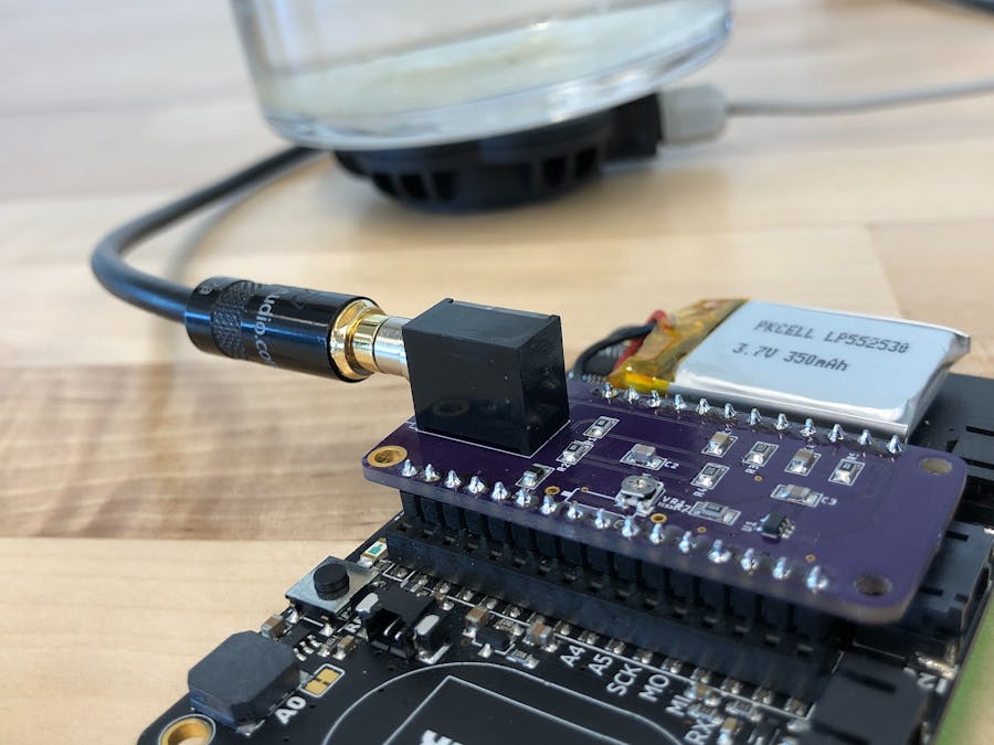
I wanted to build a TinyML model that could detect when a boat is nearby by listening for it on a hydrophone. Edge Impulse makes it easy to build ML Models that can run on an Arduino board and detect events in audio. The tricky part ended up being how to connect a hydrophone to an Arduino board. I looked around but didn't see any existing boards for powering and amplifying a microphone, like the hydrophone... so I decided to build one!
I started by modifying the Electret Microphone module from Adafruit. It powers and amplifies the microphone. I just popped off the included microphone and wired in a 3.5mm jack so I could plug in the hydrophone. While this worked... it wasn't very sturdy or compact. To fix this I decided to build my own Featherwing form factor board based on this design.
One of the the things I love about Adafruit is that they make there board designs available open source. I was able to take this design, move it over the the Feather form factor and add a 3.5mm jack instead of the microphone. I am not the best at this, but the board does work. If you have improvements to design, please make suggestions!! There is a small amount of noise, but the audio quality is more than good enough to perform ML based boat detection and has successfully worked in the field.
Building the BoardsThe first step is fab the PCB boards. I used OSHPark, which was surprisingly cheap and surprisingly fast. ( I remember having to get an expensive kit from Radio Shack and etching my own boards. Accessible Custom PCBs is one part of the future that I do like. ) If you want to just order a set of boards, I have my design shared on OSHPark. I also have the Eagle Board and Schematic files up here in case you want to improve the design (and I hope you do!).
After you get your boards back and successfully source all the parts, it is time to put them together. Since all of the parts are surface mounted, you will need to use some solder paste, small tweezer and some sort of oven to melt the paste.
The boards are made as part of a large panel at @oshpark. There are little nubs from where the boards get attached to the panel. I like to sand them off first before I start adding stuff.
Since we have a bunch of Isopropyl Alcohol lying around, I like to give them a rinse before starting. It should remove any random dust or oils on the pads.
The @maximintegrated 4466 chip has a pretty small footprint. On the test build I just dabbed and prayed. I did get this stencil, which makes everything a bit easier and it really helps make sure you only put down a small amount of paste. If there is a only a little paste, physics generally helps make sure the solder ends up in the right place and the chips is aligned. It also turns out my business card is a good solder paste squegee!
The next steps is to place all of the SMT components. I went around and placed things by categories - resistors, capacitors, and ferrite beads. Using a syringe of solder paste and a small needle, it wasn't too hard to put a dab of paste on each pad. Tweezers helped alot for placing the components. I older put paste on the bottom 2 of the 3 pads for the trimpot. When I pasted all 3 pads, the trimpot popped off during baking. It could be that the board cools and contracts slower than the trimpot.
Once all of the components are down, it is time to bake the board. This melts the solder paste and affixes the components to the board. There are fancy ovens for doing this... but we have just been using a toaster oven. It is an old one that is not used for food anymore. That said, there are still some crumbs left in it and will occasionally smoke. I used a thermometer to measure the temperature. I let it get up to 350℉ and then turn off the oven and let it slowly cool. There are much better ways to do this... but this approach has worked so far.
With the SMT components down, the next step is to do the through hole soldering to attach the header pins and the 3.5mm jack. The connection for the jack needs to be physical, in addition to electrical, so I used a bunch of extra solder. I like to use a breadboard to help make sure the header pins are straight and properly aligned. I also soldered down the pad of the trimpot.
And with that, all 5 boards are ready for testing!
With the boards done, it is time to test them! The test setup is a little… janky? I have a battery powered amplifier connected to an underwater audio transducer from Dayton audio. I put that against a flower vase full of water and place the hydrophone it. I can then playback audio and see if the Feather captures it correctly.
the first 4 boards worked great, but the 5th was a little off. After a little inspection it looked like the chip was not seated properly. With my first try ever at rework, I was able to tweak it over a little and that solved the problem!!


Comments
Please log in or sign up to comment.