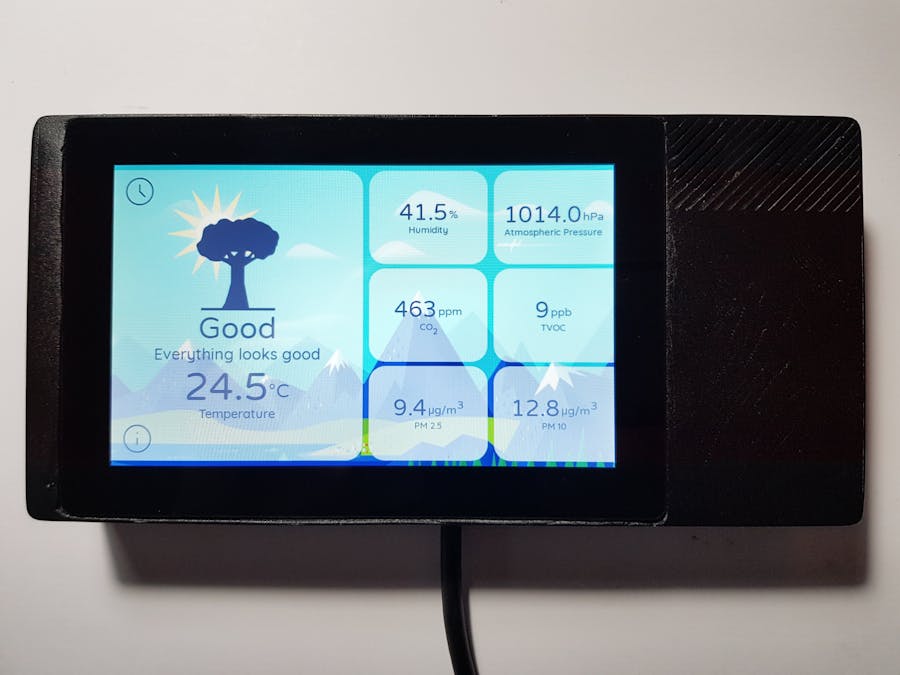
In this project you will lean how to build a device capable of measuring air quality, designed for indoor use. It displays the measures on a 5 inch touch-screen interactively and provide feedback on how to improve the air quality conditions. It uses a number of sensors:
- BME280 - temperature, humidity and atmospheric pressure sensor.
- CC811 - CO2 and TVOC (total volatile organic compounds) sensor.
- SDS011 - Dust sensor (particulate matter - PM 2.5 and PM 10).
These sensors are connected to a small computer running Android Things OS with a screen and WiFi connectivity. This project is made in a way that it should be fairly easy to adjust it according to your needs and add various improvements like online connectivity or additional sensors.
Why measure indoor air quality?
Most of the modern applications focus on measuring outdoor air pollution. This is indeed very important and useful, however most of the time in person's life is spent indoors. This is also an environment, where one is able to influence the climate using various air purifying instruments.
The negative change of indoor climate is often influenced by normal human behavior. For example levels of CO2 are increased in heavily occupied spaces with poor ventilation, levels of PM increase when cooking or smoking.
This points towards a greater need to monitor these air quality levels and be able to react to them in a timely manner.
Before StartingSection below should provide more insight into the hardware components I have used for the project in addition to the list in the hardware components section.
Sensors
I have mentioned SparkFun sensors in the hardware components, but to fit the 3-D designed case perfectly, you will need to get specifically sensors with breakout boards on the images below.
When you receive your sensors BME280 and CCS811 will most likely come with headers detached from the breakout board and you will have to solder these. This is fairly easy job and if you are not sure what you are doing, follow this tutorial. Make sure to solder these with the sensors facing outwards (see images in the next section).
Screws
Hardware components section mentions M2.5 screws. More specifically, you will need 2.5 mm diameter countersunk head machine screws with 5 mm length.
Cable
You will have to get specifically the cable mentioned in the hardware components section. This is because it needs to fit in the 3-D printed case and in the current design there is almost no tolerance.
Jumper wires
There might be multiple different versions of jumper wires available to you, but try to choose the ones with shortest black plastic protectors at the ends. I had some with longer and shorter versions and the longer ones seemed to be a bit too tight against the back lid when closed.
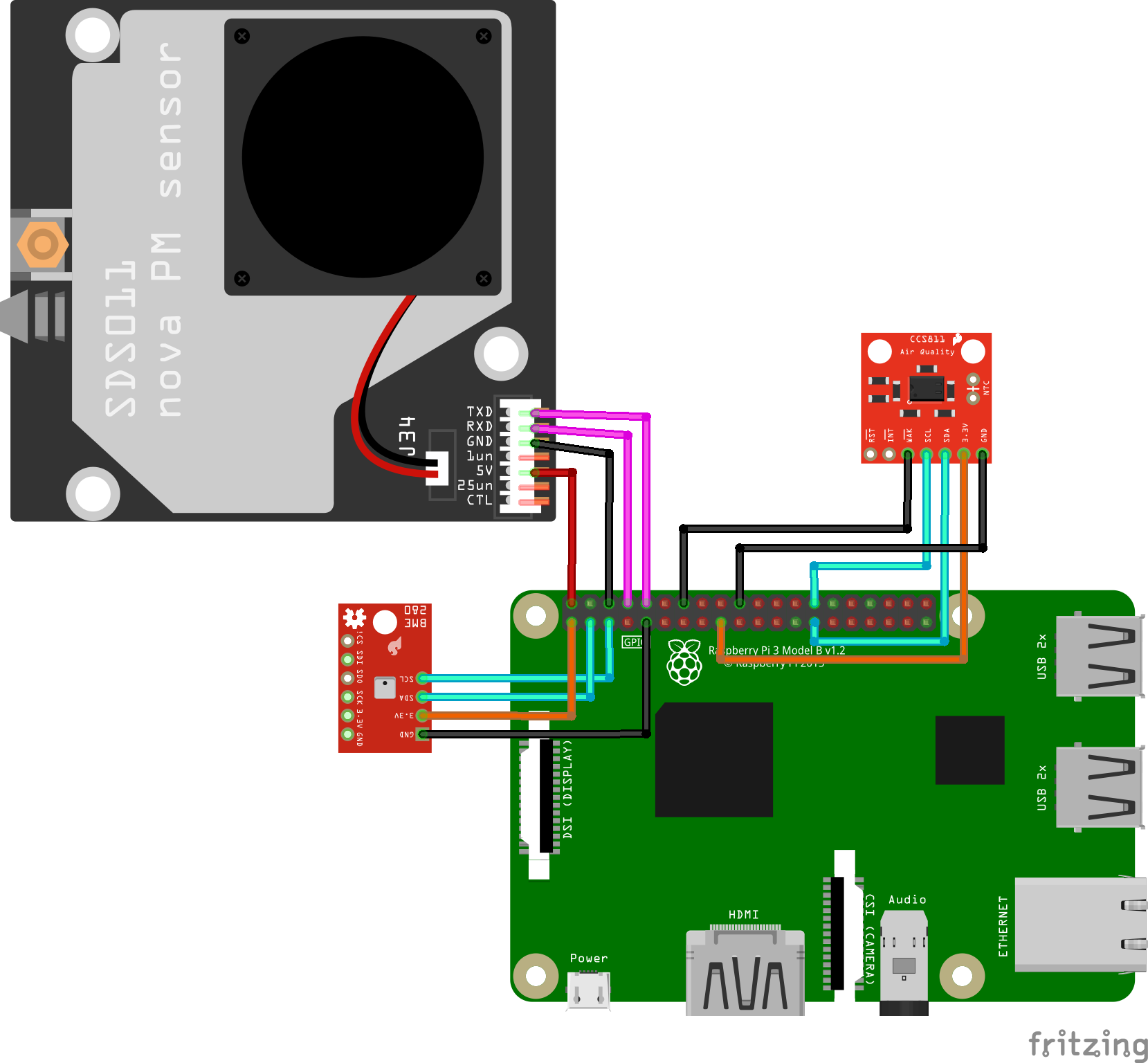
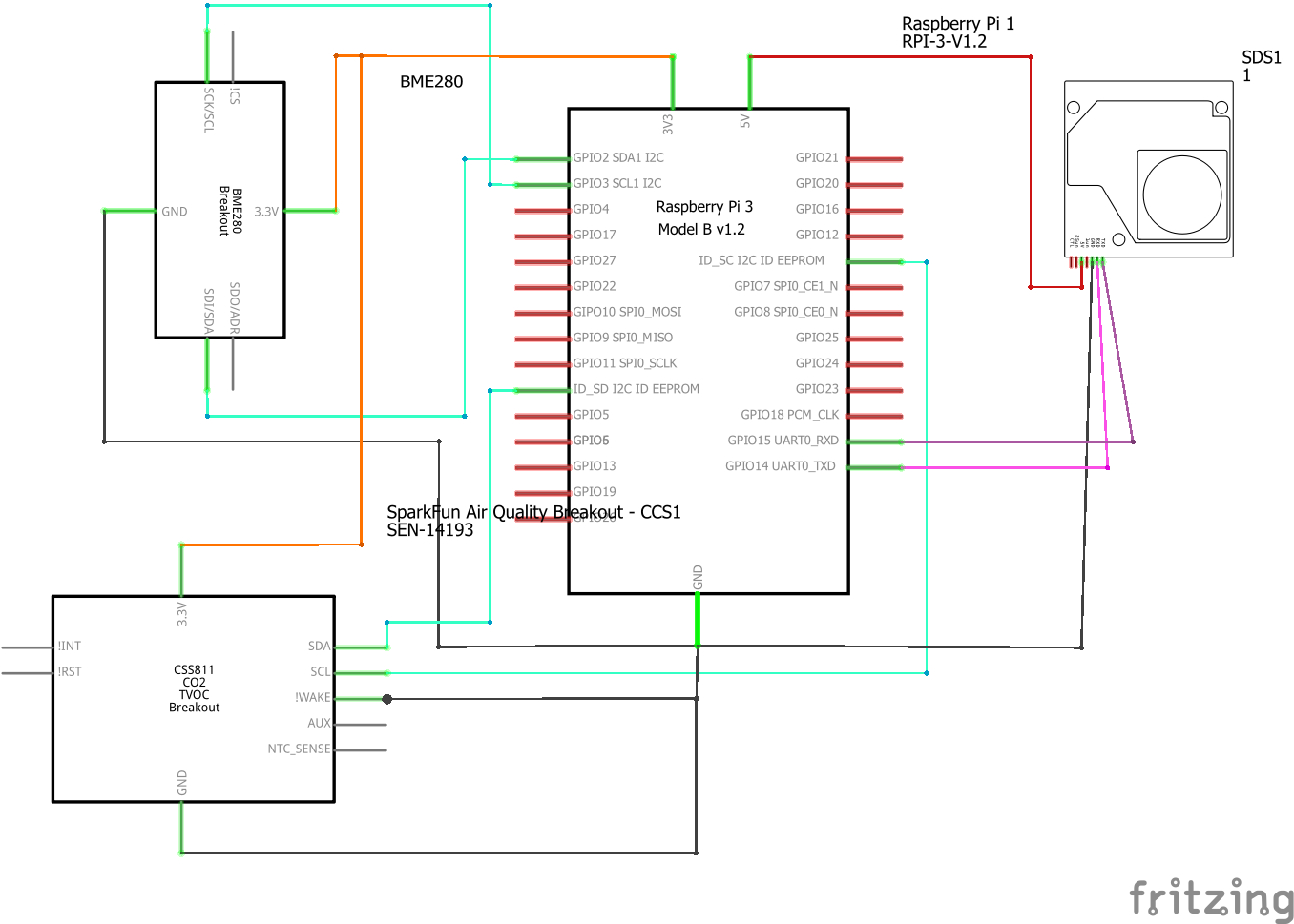
Step 1: Connect the sensors to the main boardWe will start by using the jumper wires to connect everything together. You can follow the circuit diagram here:
It shows Raspberry instead of IMX7, but pins are the same. If you need help with references for connecting the sensors to the right IMX7 pins, you can also use this pinout diagram and the attached schematic.
This step should be mostly straight forward and if you connected something wrong you will find out about it in the next step. One important thing to remember is that you have to connect the RX wire of the SDS011 to the TX wire of the IMX7 and vice versa. This is because while one device transmits (TX), the other device receives (RX). You should end up with something like this:
In the next step you will install the software and test if everything works, so also connect the screen and USB-C cable now. You will need to disconnect them later in order to be able to put everything into the 3-D printed case.
Step 2: Install the softwareThe IMX7 computer comes with the Android Things OS pre-installed out of the box. Plug the USB cable to the IMX7 and your computer. When the IMX7 boots, you should see a screen that tells you the name of the device, network that you are connected to, etc. If you are not connected to any network, you can do so now, but for this project the internet connection won't be needed.
Before proceeding to the next steps, make sure you have Android Studio installed on your computer.
If there is anything installed on the IMX7 machine, you will need to uninstall it before continuing. This can be done (on Windows) by accessingC:\Users\,<YOUR_USER>\AppData\Local\Android\Sdk\platform-tools>in your cmd and typingadb rootto get a root access to your IMX7, thenadb shell,cd data/appandls. then you will see all the packages installed on the machine. If there is something, Copy the app name - this is everything before the "-". Typeexit, then typeadb uninstall <NAME_OF_YOUR_APP>. The name is the one you copied earlier.
Go to your Android studio and check out this project from version control. Your Android Studio should detect connected IMX7 automatically and you should be able to run the project on it by pressing 'Run'. When you do this and the project runs successfully, it will stay installed on the machine even if you now unplug it from the computer.
Make sure that when the sensor info shows up on the screen, it looks similar to one of these:
CO2 and TVOC values might jump around for a while, but eventually they will start showing values above 400 and 0 respectively.
If something doesn't work as described, reconnect the sensors, try again and observe Logcat.
Here you can also adjust your thresholds for the notifications of varying levels of air quality. Simply change the values in the Constants.kt file in your Android Studio.After making sure that everything works, we can proceed to 3-D print the case before the final assembly.
Step 3: 3-D PrintingFor this step, you will need a file for a lid an a file for a case from the attachments. If you don't want to edit anything, you can just download these files and import them into a slicing program used by your 3-D printer. I have printed with CraftBot, so I have used their CraftWare slicing software to make a file with the instructions for the printer.
If you are not sure where to get a 3-D printer, check if there is a FabLab near you. I'm lucky to have one with 3-D printers near me and they were extremely helpful with everything!
You might notice that the 3-D design in the attached file is slightly different from what I have printed. I made some mistakes in the design initially and had to use a Dremel tool to grind down some excess plastic. This should already be fixed in the latest design so the process should be smoother for you.
I have not printed this new version yet, so if you do it and find some more areas for improvements, share them in the comments. One of the things I have tried to improve is the air flow to the BME280 and CCS811 sensors as they were very slow to pick up changes in air quality and there was some unwanted thermal transfer from the IMX7.
If you can, 3-D print in filament color of your preference, I had only white filament, so I have later spray-painted the print black.
Your print will most likely have supports for overhanging parts, so clean these up and sand down excess plastic where needed. Now you should be ready to assemble everything together.
Step 4: Final assemblyStart by put the screen in the opening in the front part of the case. Use glue or tape to fix it in place (depending on how likely it is that you will have to disassemble the device again). Now, place the antenna and screw it in.
Put in the IMX7 with the USB cable plugged in. Two connectors to the screens are a bit tricky to plug in, so be patient and careful not to break them. When you have the screen plugged in, secure the IMX7 with 3 screws, this should suffice.
Put the BME280 and CCS811 to their designated spots in the corner of the case. If the width doesn't fit perfectly, you will need to sand down a bit from the sides. Screw them in.
Now you are ready to put in the SDS011. Secure it with 3 screws.
Place the lid and screw it in.
ConclusionIn an ideal case, you will now plugin the USB cable of your device to power and everything should work correctly. There is a chance this doesn't happen, in this case try to work back and identify the problem. Double-check if everything is connected correctly.
On the screen you will have an option to change the interval of the measurements. Default one is 1 second. You will also be able to see more info on what each measurement means.
After you have built this device, I encourage you to modify it according to your needs and desires. Add online connectivity, more sensors, graphs, air quality forecast... Share your experiences in the comments!


_3u05Tpwasz.png?auto=compress%2Cformat&w=40&h=40&fit=fillmax&bg=fff&dpr=2)

Comments
Please log in or sign up to comment.