


Hardware components | ||||||
_ztBMuBhMHo.jpg?auto=compress%2Cformat&w=48&h=48&fit=fill&bg=ffffff) |
| × | 1 | |||
 |
| × | 4 | |||
 |
| × | 1 | |||
 |
| × | 1 | |||
 |
| × | 1 | |||
 |
| × | 1 | |||
 |
| × | 13 | |||
 |
| × | 4 | |||
 |
| × | 1 | |||
Object of Game
To remember the colour sequence of lights (LEDs) shown and then re-enter these in the correct order within a fixed time via associated button switches.
Game Play Cycle
On microcontroller start up, the game continuously runs through game cycles. A game cycle comprises the follow steps:
- All four LEDS will flash four times, signifying a light sequence is about to be shown.
- A light sequence is then shown - between four and six LEDs will be randomly illuminated.
- At the end of the sequence, the player then has 10 seconds to enter the sequence on the button switches in the correct order.
- There are three possible outcomes:
1. the correct sequence is entered within the play time. In this case, the GREEN LED is flashed five times - SUCCESS.
2. the incorrect sequence is entered within the play time. In this case the RED LED is flashed five times - FAIL.
3. a sequence is not entered within the play time. In this case, the BLUE LED is flashed five times - FAIL.
- After the play cycle, the game resets, selecting a new random sequence and then restarts - play continues as above.
Observations -Sketch
- Switch reading is performed by a switch read function ('read_switch') in a non-exclusive way and incorporating debounce. The same function is used to read any specified button switch, via its function parameter. The 'read_switch' function parameter defines the entry of a switch's fixed and real-time control information held within a 'struct' data type.
Observations -Circuit
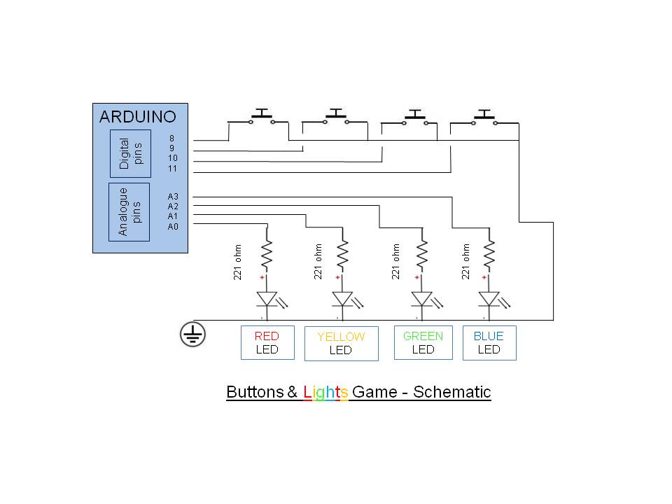
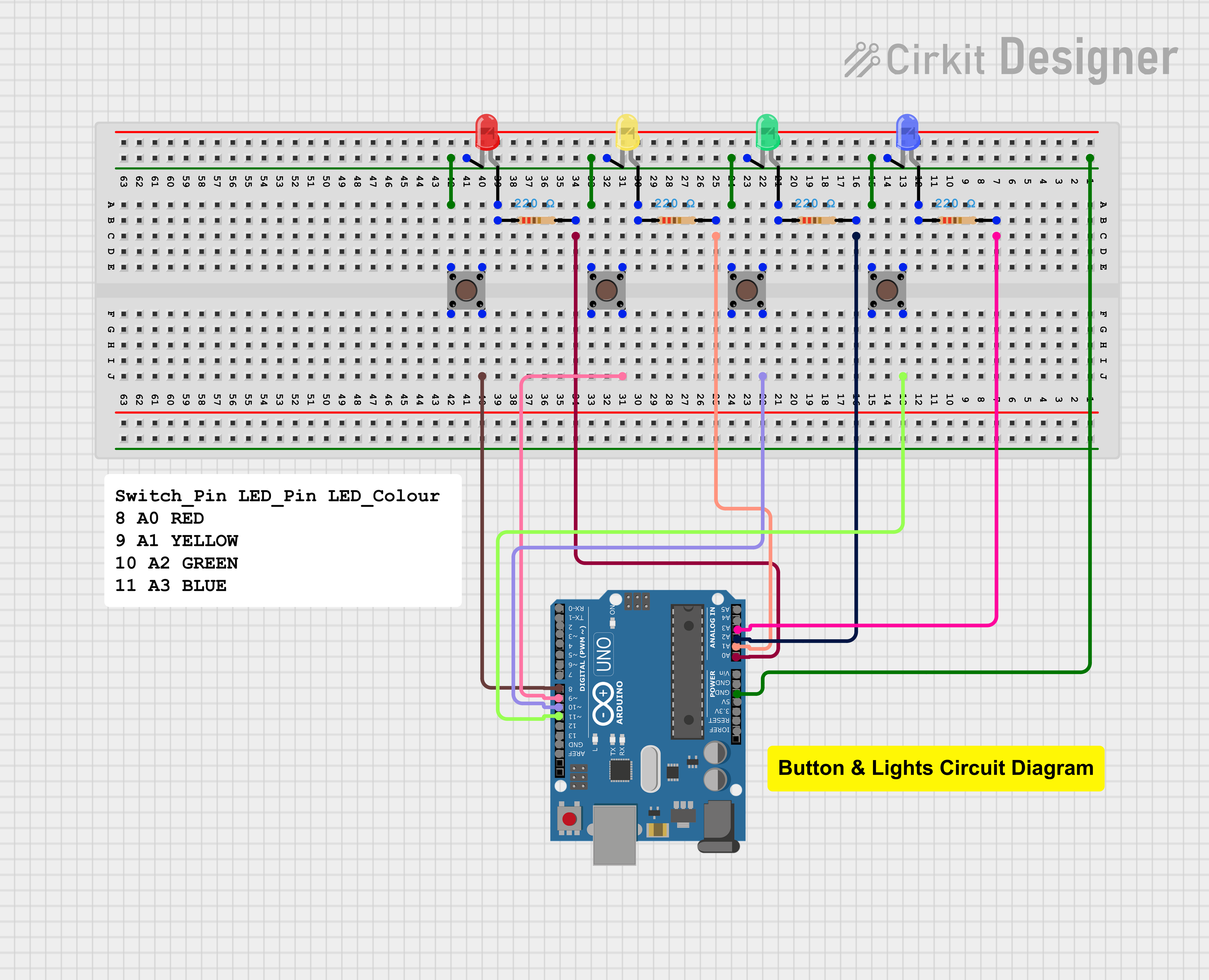
- The schematic for the game's circuit design is very straight forward - one button switch to one LED. It can be easily wired up on a breadboard - see Component List and Schematic Diagram below.
- Switches are wired without pull down resistors - one side to a digital pin, the other to ground (0v). The digital inputs are initialised as INPUT_PULLUP, meaning that when the attached switch is operated the pin will go LOW. For a full appreciation of different circuit types for button switches see UnderstandIng and UsIng Button SwItches, the basIcs.
- For the game to be visually appealing and to help remembering a light sequence, four different coloured LEDS are used, each associated to a button switch. The association of Arduino inputs/outputs (LEDs) is as follows;
Digital Input: 8, Analogue Output: A0, LED Colour: RED (fail)
Digital Input: 9, Analogue Output: A1, LED Colour: YELLOW
Digital Input: 10, Analogue Output: A2, LED Colour: GREEN (success)
Digital Input: 11, Analogue Output: A3 LED Colour: BLUE (out of time)
Configurability
The game, as provided, is configured to display a sequence of between four and six lights and a response (guess) time period of 10 seconds.
These may be varied, as required, by changes to two sketch declarations, as follows:
- Varying the number of lights in a sequence - change the macro '#define max_sequence' to a value >= 4 (it is set to 6 in the supplied sketch). Note that there is no practical limit to the sequence size, but bear in mind to increase the guess time period commensurate to the value selected (next point).
- Varying the time within which a guess is to be completed - change the variable ' int guess_duration' to be the time period in milliseconds.
SuggestionsForFurtherDevelopment
The game can be extended in many ways. Some suggestions are:
1. Automatically and progressively shortening the guess period, say by a second each three game cycles, until a given minimum interval is reached. The guess period can then be reset to its initial value and play continue as before, or otherwise.
2. Adding further button switches and LEDs. The code design is structured so that this should be straight forward - extend the declarations '#define num_switches', 'struct switch_control ' and 'int leds[num_switches]' as required.
3. Adding a buzzer, and playing different tones for success, fail and out of time, each to accompany the respective coloured LEDs. Instead of bland tones, play different melodies.
4. As for suggestion 3, but add a potentiometer to control the volume of the buzzer.
5. Etc., there are many opportunities for extending the basic game play.
And Finally
Enjoy making and playing the game and, if you are of a mind, try some of the suggested changes.
Further ReadingYou might also find these contributions interesting and useful, by the same author:
- UnderstandIng and UsIng Button SwItches, the basIcs - button switches, a simple but often tricky piece of kit. The tutorial provides in ins and outs of implementing a simple button switch, with flexibility to explore differences in circuit design, different reading methods and debouncing.
- Interrupts Driven Button Switches - an approach and example of tying a button switch to an external interrupt.
- Toggle Switches - how to reliably read a toggle style switch.
- External Interrupts, a generic framework supporting concurrent asynchronous multiple interrupts. Configure multiple external interrupts with different characteristics and add code to provide post-interrupt asynchronous processing.
- Programmatic Timed Reminder Alerting, a programmatic framework for both elapsed and real-time asynchronous alerting. Define any number of reminder alerts (sub second to hours) and process asynchronously.
Other Online Resources

Comments
Please log in or sign up to comment.