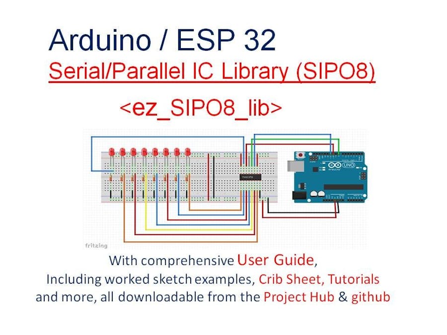
Arduino microcontrollers are great for offering readily usable digital and analogue I/O pins for connecting to the outside world; some boards have few, some have many (eg MEGA 2560). But sometimes there just aren't enough for our project or we want to keep their use to a minimum. This is where the humble and low cost Serial-Parallel Integrated Circuit (SIPO IC) comes to our rescue!
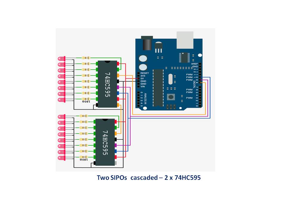
SIPO ICs offer us significant reductions in microcontroller pin usage, a factor of at least 3:8 for a singly wired 8bit IC and much, much better ratios if we connect them in a cascade (daisy chain). For example, if we cascade 4 SIPO ICs this improvement increases to 3:32! Even greater efficiencies can be leveraged.
If you have already dabbled or used in anger SIPO ICs in your projects then you will know that they can present their own challenges - usually lots of wiring, difficult to use software drivers/methods to mention just two. So anything that improves our lot would be a good thing? Of course. This is where the ez_SIPO8 library can provide a considerable range of easy to use functions and methods that can make project design using SIPO ICs a dream. Even more than that, the SIPO8 design architecture can lead to innovation and highly scalable project designs.
The SIPO8 non-blocking library has been designed to support up to 255 8bit SIPO ICs, configured into banks, each of which may contain (map) from one to many individual SIPO ICs in a cascaded arrangement.
Indeed, the theoretical maximum number of SIPO outputs that the library can support is a massive 2040 output pins, arranged into banks of SIPO ICs of any number. A single bank of SIPO ICs requires its own 3-wire microcontroller digital pins to drive it, but a single such interface can support banks of any size, even beyond eight SIPO ICs which seems to be a current limitation of some implementations.
By using the SIPO8 library in your projects you will be able to design and craft straight forward, innovative and elegant solutions incorporating SIPO ICs, even if it is just one, or dozens.
The following article provides a synopsis of the SIPO8 library, but a complete and comprehensive description including worked examples can be found in the User Guide. In addition, understanding of the SIPO8 library is further supplemented with a summarised crib sheet and six standalone tutorials each with associated downloadable sketches/examples.
The SIPO8 Design ObjectivesFor those readers who have seen some of my previous articles, eg ez_switch_lib, you will know that I like to inject a quotation or two not necessarily from the world of computing (it is surprising how these two worlds can align!). Here we go...
A computer is a machine for constructing mappings from input to output. Michael Kirby
Creativity is an input to innovation and change is the output from innovation. Braden Kelley
Through great input you get great output. RZA
These three quotations are particularly pertinent in nicely summarising the essence of the design architecture of the SIPO8 library. At the outset, a number of key objectives were established for the design of the SIPO8 library, these being a library that provided/supported:
- a design that would maximise the number of physical output pins that could be supported/driven by the standard range of Arduino microcontrollers
- a representation of physical SIPO ICs and their output pins into the virtual, allowing independent programmatic manipulation of outputs
- a logical, flexible and straight forward design - one that would allow the end user developer to easily manage/control a large number of outputs discretely, or as a set of outputs; a design architecture that would be modular and granular
- recognition that many common SIPO ICs have a standard hardware interface which could be leveraged and used to good advantage – SIPO IC hardware transparency
- a solution that would be scalable, allowing freedom for the end user to incorporate many SIPO ICs in their project design
- a solution that provides support for many 100s of outputs
- a rich set of functional capabilities to define, control and drive SIPO ICs, individually or in a cascaded arrangement, as individual banks
- the capability to group, through cascading/daisy chaining, any number of SIPO ICs in a single arrangement (bank), even beyond eight ICs in a single cascade
- the capability to define any number of differently sized SIPO banks, single or multiple and cascaded SIPO ICs
- the capability to work with SIPOs of different and mixed bit/pin size, e.g. 8, 16, 32 or 64bit SIPO ICs
- tools for the end user to examine key data during development
The SIPO8 library meets and exceeds all of the above design objectives and, whilst under development, new capabilities also became evident, not foreseen at the outset (e.g. bank interleaving).
The end result is a non-blocking library that offers a wide range of features and capabilities to command and control any number of SIPO ICs, wired singly or in cascades.
Key FeaturesIn summary, the key features of the SIPO8 library are:
- virtual mapping of all physical SIPO IC output pins
- ability to create multiple banks of SPIO ICs, of varying bank size
- rich set of functions/methods to manage and update virtual SIPO output pins using absolute (array level pin addressing) and relative pin/bank addressing (bank level pin addressing)
- updating of physical SIPO IC output pins as an entire array or individually as separate banks
- SIPO IC transparency - any SIPO IC 8bit, 16bit, 32bit, etc that conforms to same 3-wire interface and cascade capabilities as the standard 74HC595 IC
- the ability to interleave different banks of SIPO ICs using the same 3-wire interface
- any number of user definable timers
- comprehensive reporting of array pool/bank status and associated parameters
The problem in promoting something like a new library is that it is difficult to fully get across its scope and depth. The SIPO8 library provides many helpful functions/methods for configuring SIPO ICs, too many for a story board article such as this. The full potential can only be appreciated by reading the User Guide and running through its examples and the associated tutorials. I will therefore conclude this article with a couple of straight forward example sketches, or 'tasters':
Sketch 1 will sample the status of 6 toggle switches and set their respective SIPO IC pins LOW/HIGH, according to their current state (on/off). In addition, SIPO IC pin 7 will be used as a 'sketch is running ok' or 'heart beat' indicator and will flash with each sample cycle. SIPO IC pin 6 will not be used.
Sketch 2 will demonstrate a strobing set of LEDs.
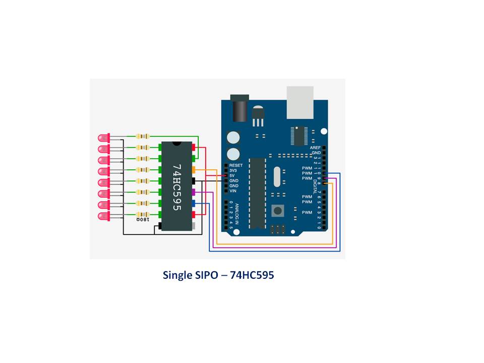
Before we get into the sketches, you will need to set up test harness with a breadboard, a SIPO IC (eg 1 x 74HC595 shift register), 8 X 220- ohm resistors (not 180 ohm shown in the diagram), 8 x LEDs, 1 x microcontroller (eg Arduino UNO) and wires sufficient for the job! Then wire up as follows:
Sketch 1 - Switch Status Display
/*
  Ron D Bentley, Stafford, UK
  April 2021
  Example sketch 1 for Arduino Community story board
  The sketch reads a number of toggle switches which are in one of two
  states - on(HIGH) or off(LOW).
  Each switch is mapped to a SIPO bank pin as follows:
  switches 0-5 -> bank pins 0-5
                  bank pin 6 is not used
                  bank pin 7 is used as a sketch running indicator,
                             or 'heart beat'
  Note that the switches are 'read' periodically sampled by a dummy
  function using the SIPO8 timers feature. The code is non-blocking.
  This example and code is in the public domain and
  may be used without restriction and without warranty.
*/
#include <ez_SIPO8_lib.h>
#define Max_SIPOs        1
#define Max_timers       1
#define sample_time    500  // interval period between sampling sensors
#define num_switches     6  // number of sensors requiring testing/reading in each cycle
// initiate the class for max SIPOs/timers required
SIPO8 my_SIPOs(Max_SIPOs, Max_timers);
uint8_t bank_id;
// dummy read switch function - returns a random staus for given switch
// number, based on switch's current status
bool read_switch_status(uint8_t Switch) {
 randomSeed(analogRead(A0)*analogRead(A2)); // keep changing seed
 if (random(0, 4) == 0)return !my_SIPOs.read_bank_pin(bank_id, Switch);
 return my_SIPOs.read_bank_pin(bank_id, Switch);
}
void setup() {
 Serial.begin(9600);
 // create 1 bank of Max_SIPOs
 // params are data pin, clock pin anf latch pin, number SIPOs
 bank_id = my_SIPOs.create_bank(8, 10, 9, Max_SIPOs);
 if (bank_id == create_bank_failure) {
   Serial.println(F("failed to create bank"));
   Serial.flush();
   exit(0);
 }
 my_SIPOs.print_SIPO_data();  // report on global SIPO8 params
}
// Scan all defined switches and set their respective bank pin status, LOW/HIGH.
// Switches/bank pins layout:
// Switch associated bank pins run from 0 to num_switches-1, inclusive (5) and
// are used to indicate respective switch status,
// bank pin 6 is not used and bank pin 7 is used to provide
// a 'heart beat' to indicate that the sketch is running.
void loop() {
 my_SIPOs.set_all_array_pins(LOW); // ensure we start with clear array pool/bank
 my_SIPOs.xfer_array(MSBFIRST);
 my_SIPOs.SIPO8_start_timer(timer0); // start the sample timer
 do {
   if (my_SIPOs.SIPO8_timer_elapsed(timer0, sample_time) == elapsed) {
     my_SIPOs.SIPO8_start_timer(timer0); // reset/restart the timer
     // read each switch and set its virtual SIPO pin in the bank
     my_SIPOs.invert_bank_pin(bank_id, 7); // flash 'heart beat'
     for (uint8_t Switch = 0; Switch < num_switches; Switch ++) {
       my_SIPOs.set_bank_pin(bank_id, Switch, read_switch_status(Switch));
     }
     my_SIPOs.xfer_bank(bank_id, MSBFIRST); // update the physical SIPO pins
   }
 } while (true);
}
A quick summary of what the functions are/do:
SIPO8 my_SIPOs(...) - sets up the SIPO8 virtual environment, creating an array pool of the specified number of SIPO output pins plus the number of timers required.
create_bank(...) - creates a bank of SIPO output pins of the specified size, here 1 x 8 pins, which will be referenced from 0 to 7.
print_SIPO_data() - displays to the serial monitor all global SIPO8 data including all defined bank parameters
set_all_array_pins(...) - sets every active SIPO output pin to the specified parameter, LOW or HIGH.
xfer_array(...) - shifts out the entire array of active SIPO output pins in the direction of shift given.
SIPO8_start_timer(...) - starts the specified timer.
SIPO8_timer_elapsed(...) - checks if the specified timer has reached/exceeded the specified elapse time (milliseconds).
create_bank_failure/elapsed - library macro values accessible to end users (see User Guide/Crib Sheet).
invert_bank_pin(...) - inverts the existing status of the pin at the specified relative bank pin address.
set_bank_pin(...) - sets the pin at the specified relative bank pin address to the given status value.
xfer_bank(...) - shifts out the specified bank of SIPO outputs in the direction of shift given.
The above sketch can be downloaded from the code section below.
Sketch 2 - Strobing LEDs
/* Ron D Bentley, Stafford, UK
  April 2021
  Example sketch 2 for Arduino Community story board
  This sketch strobes a number of LEDs driven by a SIPO IC, 8 output pins
  forwards and backwards at a defined frequency.
  This example uses relative bank addressing with pin set and invert functions.
  Ron D Bentley, Stafford, UK
  April 2021
  This example and code is in the public domain and
  may be used without restriction and without warranty.
*/
#include <ez_SIPO8_lib.h>
#define Max_SIPOs  1 // 1 x SIPOs - provides 8 output pins
#define Max_timers 0 // no timers required, will use delay
#define data_pin    8
#define clock_pin  10
#define latch_pin   9
#define strobe_frequency     50  // milli seconds, delay frequency
// initiate the class for max SIPOs/timers required
SIPO8 my_SIPOs(Max_SIPOs, Max_timers);
int bank_id;  // used to keep the SIPO bank id
void setup() {
 Serial.begin(9600);
 // create a bank of 'Max_SIPOs' using create_bank function:
 bank_id = my_SIPOs.create_bank(data_pin, clock_pin, latch_pin, Max_SIPOs);
 if (bank_id == create_bank_failure) {
   Serial.println(F("\nfailed to create bank, terminated"));
   Serial.flush();
   exit(0);
 }
 my_SIPOs.print_SIPO_data();  // report on global SIPO8 params
 // start by setting all SIPO outputs to low (off) in the SIPO bank
 my_SIPOs.set_bank_SIPO(bank_id, 0, 0b00000000); // only 1 SIPO in bank,index 0
 my_SIPOs.xfer_bank(bank_id, MSBFIRST);
}
void loop() {
 //strobe example, strobe bank_id pins forward and back
 bool msb_or_lsb = MSBFIRST; // pick an initial strobe direction
 uint8_t num_pins = Max_SIPOs * pins_per_SIPO;  // lots of ways to do this
 do {
   for (uint16_t pin = 0; pin < num_pins; pin++) {
     my_SIPOs.set_bank_pin(bank_id, pin, HIGH); // set strobe pin
     my_SIPOs.xfer_bank(bank_id, msb_or_lsb);   // update physical SIPO bank
     delay(strobe_frequency);
     my_SIPOs.invert_bank_pin(bank_id, pin);    // invert strobe pin - alternative to set_bank_pin(low)
     my_SIPOs.xfer_bank(bank_id, msb_or_lsb);   // update physical SIPO bank
   }
   msb_or_lsb = !msb_or_lsb; // switch strobe direction
 } while (true);
}
A quick summary of SIPO8 functions new in Sketch 2 :
set_bank_SIPO(...) - sets the specified 8 pin SIPO at the relative SIPO address to the given 8bit pin value. Equivalent to 8 x set_bank_pin calls!
pins_per_SIPO - a library macro value accessible to end users (see User Guide/Crib Sheet).And Finally
Hopefully, at this point, you will know if the SIPO8 library is worthy of further exploration. Certainly, if you have SIPO IC projects in the pipeline, as a hobbyist or as a professional, then the library will be very helpful in developing these.
You will find further useful material as below:
- User Guide - the full works, technical detail plus examples
- Crib Sheet - a synopsis of... everything!
- Tutorials - a set of six tutorials to help understanding and use of the library, absolute addressing, relative addressing, using timers, cascading multiple shift registers, bank interleaving and a final tutorial that provides deeper understanding
Enjoy!
Further ReadingYou might also find these contributions interesting and useful, by the same author:
- A general switch library (ez_switch_lib), suitable for most switch types and wiring schemes, incorporating novel features
- UnderstandIng and UsIng Button SwItches, the basIcs - button switches, a simple but often tricky piece of kit. The tutorial provides in ins and outs of implementing a simple button switch, with flexibility to explore differences in circuit design, different reading methods and debouncing.
- Interrupts Driven Button Switches - an approach and example of tying a button switch to an external interrupt.
- Toggle Switches - how to reliably read a toggle style switch.
- Buttons & Lights Game - a bit of fun using button switches and LEDs.
- External Interrupts, a generic framework supporting concurrent asynchronous multiple interrupts. Configure multiple external interrupts with different characteristics and add code to provide post-interrupt asynchronous processing.
- Programmatic Timed Reminder Alerting, a programmatic framework for both elapsed and real-time asynchronous alerting. Define any number of reminder alerts (sub second to hours) and process asynchronously.


_ztBMuBhMHo.jpg?auto=compress%2Cformat&w=48&h=48&fit=fill&bg=ffffff)


Comments
Please log in or sign up to comment.