


Hardware components | ||||||
_ztBMuBhMHo.jpg?auto=compress%2Cformat&w=48&h=48&fit=fill&bg=ffffff) |
| × | 1 | |||
 |
| × | 1 | |||
 |
| × | 8 | |||
 |
| × | 8 | |||
 |
| × | 1 | |||
Software apps and online services | ||||||
 |
| |||||
If you have arrived at this article by random means and not via its starting point, then you may find that it may not make much sense. This is because this article is one of several (six) tutorials to aid and assist in understanding the use of the ez_SIPO8_lib library in managing and controlling Serial-in/Parallel-out ICs (SIPOs) shift registers, for example 74HC595 chips.
If you wish to link to the start of the tutorial then please follow this link (Tutorial Start), otherwise, please read on...
A tutorial to consolidate understanding and use of the ez Serial-in/Parallel-out IC Library (ez_SIPO8_lib) - Tutorial 3, Using Timers. If you wish to link to the tutorial starting article then follow this link: Tutorial Start.You can access and download the User Guide, Crib Sheet and the original ez_SIPO8_lib article by following these links below: - ez_SIPO8_lib User Guide- ez_SIPO8_lib Crib Sheet- Read the full ez_SIPO8_lib articleIntroduction to the TutorialIn this third tutorial we will build on our Tutorial 1 and 2 experiences and look at how we can use the SIPO8 library timer features to control the status of SIPO IC output pins. We shall make use of the same physical SIPO IC circuit we set up in Tutorial 1.
The tutorial will configure eight SIPO8 timers, one for each of the SIPO output pins and use these to control the rate at which we wish to flash the respective connected LEDs on/off. The approach will be flexible allowing us to easily vary flash rates and output pin ordering.
ObjectivesWe shall concern ourselves with creating a virtual SIPO environment in which we can apply further basic principles. In particular we shall learn:
1. how we can wire up and connect a single 74HC595 IC (SIPO) to a microcontroller (see Tutorial 1, if you have not already done so)
2. how we can use in-built SIPO8 library timer functions to control and drive physical SIPO outputs
3. the further use of SIPO8 library functions
4. witness the outputs of the sketch – variable flashing LEDs and serial monitor SIPO data.
If you ran through Tutorials 1 and 2 and still have your components set up as for that tutorial, then skip to The Code/Sketch, otherwise continue as below.
Kit ListGather together the following components:
- 1 x Arduino UNO - The design uses an Arduino UNO, but any suitable microcontroller (Arduino or clone) will do, providing it is able to support the pin out requirements for driving the SIPO interface and power requirements
- 1 x Breadboard - Small or large, whatever you have to hand
- 1 x 74HC595 IC - 8-bit SIPO IC, or other clone providing it is genuinely ‘plug-compatible’
- 8 x LEDs - Whatever you have around
- 8 x Resistors, 220 ohm - One per LED. Use 220 ohm resisters and ignore the suggested 180 ohm values in the wiring diagrams
- Connecting wires - Short/long or breadboard wire connectors, whatever suits
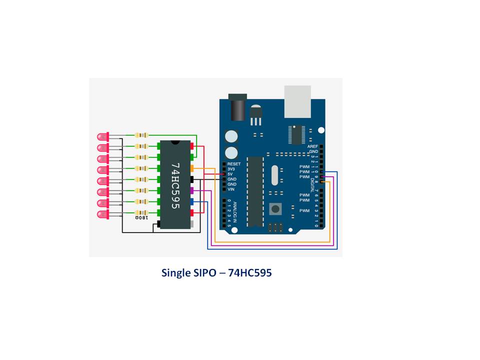
Which end is which? Well, notice that the 74HC595 has a notch at one end, here at the top of the diagram. Pin numbering starts at 1 at the top left and continues down the left hand side and the around the bottom of the IC rising to the top right hand side to pin 16:
Every bank of SIPO ICs you connect to the microcontroller requires a 3-wire digital interface (3WI). As this tutorial concerns a single SIPO IC then we shall only need one x 3WI. The table below suggests pin mapping between the microcontroller and the SIPO IC for this tutorial, but you may choose what microcontroller digital pins you wish. If you do choose different pins then be sure to alter the sketch function create_bank call in setup().
- UNO pin 8 to SIPO pin 14 - SIPO Data Pin
- UNO pin 9 to SIPO pin 12 - SIPO Latch Pin
- UNO pin 10 to SIPO pin 11 - SIPO Clock Pin
- UNO pin +5v to SIPO pins 10, 16 - Power to the SIPO
- UNO GND pin to SIPO pins 8, 13 - Return ground (0v)
Using the following diagram, wire up all of the components, taking care to get the output/input connections correct:
Notice that the only 74HC595 IC pin not to have anything connected is pin 9, QH’. This is used as the serial output pin to connect to the serial input pin, 14SER, of the next SIPO 74HC595 in a cascade.
The Code/SketchNow that’s done, let’s look at a sketch using timers to control variable flashing LEDs, download the sketch, compile and upload.
//
//   Tutorial 3 - use of ez_SIPO8 library,
//   1x physical SIPO, and use of SIPO8 timers to control SIPO outputs with time
//
//   Ron D Bentley, Stafford, UK
//   April 2021
//
//   This example and code is in the public domain and
//   may be used without restriction and without warranty.
//
#include <ez_SIPO8_lib.h>
#define Max_SIPOs  1  // one virtual SIPO for this tutorial
#define Max_timers 8  // 8 timers required to map a complete 8bit SIPO
// initiate the class for Max SIPOs/timers required
SIPO8 my_SIPOs(Max_SIPOs, Max_timers);
int bank0_id;  // used to keep the SIPO bank id
//
// setup pin/LED flash data
uint8_t timer;
uint32_t timer_intervals[Max_timers] = {
 300, 400, 500, 600, 700, 800, 900, 1000 // millisecond elapse timer values
};
uint8_t timer_pins[Max_timers] = {
 0, 1, 2, 3, 4, 5, 6, 7 // SIPO output pin absolute addresses
};
void setup() {
 Serial.begin(9600);
 // create bank, params are:
 // data pin, clock pin, latch pin, number of SIPOs this bank
 bank0_id = my_SIPOs.create_bank(8, 10, 9, 1);
 if (bank0_id == create_bank_failure) {
   Serial.println(F("\nfailed to create bank"));
   Serial.flush();
   exit(0);
 }
 // print the bank data for confirmation/inspection
 my_SIPOs.print_SIPO_data();
}
void loop() {
 // start by setting all SIPO outputs to low (off)
 my_SIPOs.set_all_array_pins(LOW);// set all declared virtual output pins LOW/off
 my_SIPOs.xfer_array(LSBFIRST);   // move virtual pin statuses to real SIPO output pins
 //
 // start all timers
 for (timer = 0; timer < Max_timers; timer++) {
   my_SIPOs.SIPO8_start_timer(timer);
 }
 timer = 0; // start checking at first timer
 do {
   // check each timer for elapse and, if elapsed, invert the timer's output pin
   // and reset the timer
   if (my_SIPOs.SIPO8_timer_elapsed(timer, timer_intervals[timer]) == elapsed) {
     my_SIPOs.invert_array_pin(timer_pins[timer]); // invert the pin associated with this timer
     my_SIPOs.xfer_array(MSBFIRST);// update physical SIPO outputs
     my_SIPOs.SIPO8_start_timer(timer);// reset/restart the current timer
   }
   timer++;  // move on to next timer
   if (timer >= Max_timers) timer = 0; // wrap around to beginning
 } while (true);
}
To Notice:
1. that we automatically configure the eight timers we need for our purposes (one per output port/LED) as a part of the SIPO8 class instantiation (second parameter, here 8). We can create up to255 timers if desired, but that’s a lot!
2. we declare and preset two arrays to define the flash rate intervals (in milliseconds) and the associated absolute output pin numbers we wish to control –
uint32_t timer_intervals[Max_timers], and
uint8_t timer_pins[Max_timers]
These arrays allow us to easily vary flash rates and change the order of output pins as we desire
3. there are three SIPO8 library functions that allow us to utilise and control SIPO8 timers, these being:
SIPO8_start_timer(timer)
SIPO8_timer_elapsed(timer, timer_intervals[timer])and
SIPO8_stop_timer(timer)
Each timer function takes an initial parameter which is the timer number we wish to reference. However, in the case of SIPO8_timer_elapsed then this function has a second parameter which is the elapsed time interval we wish to check against for elapsed time (milliseconds), here it is the interval for the timer to run before it expires. Note that this second parameter is an unsigned 32 bit variable, so watch how you define these values in your sketches.
The sketch does not use the SIPO8_stop_timer function, but it is fully documented in the User Guide and Crib Sheet.
4. the code controlling the flash cycle is succinct and simply structured.
You should see the LEDs each flashing at the rates defined by the presets in our timer_intervals array.
Check the serial monitor, it should look like this:
SIPO global values:
pins_per_SIPO = 8
max_SIPOs = 1
bank_SIPO_count = 1
num_active_pins = 8
num_pin_status_bytes = 1
next_free bank = all SIPOs used
Number timers = 8
Bank data:
bank = 0
    num SIPOs = 1
    latch_pin = 9 clock_pin = 10 data_pin = 8
    low_pin = 0 high_pin = 7
Before finishing this tutorial, have a go at varying the flash rates and/or output pin ordering.
That is the end of Tutorial 3, which I hope you found instructional. A copy of the tutorial can be downloaded from github here.
If you are ready and wish to go on to the next tutorial then follow this link: Tutorial 4, Cascading SIPOs, but if you wish to link to the tutorial starting article then follow this link: Tutorial Start.

Comments
Please log in or sign up to comment.