


Hardware components | ||||||
_ztBMuBhMHo.jpg?auto=compress%2Cformat&w=48&h=48&fit=fill&bg=ffffff) |
| × | 1 | |||
 |
| × | 1 | |||
 |
| × | 8 | |||
 |
| × | 8 | |||
 |
| × | 1 | |||
 |
| × | 1 | |||
Software apps and online services | ||||||
 |
| |||||
If you have arrived at this article by random means and not via its starting point, then you may find that it may not make much sense. This is because this article is one of several (six) tutorials to aid and assist in understanding the use of the ez_SIPO8_lib library in managing and controlling Serial-in/Parallel-out ICs (SIPOs) shift registers, for example 74HC595 chips.
If you wish to link to the start of the tutorial then please follow this link (Tutorial Start), otherwise, please read on...
Q&As - What is/How Can I/How Do I...A tutorial to consolidate understanding and use of the ez Serial-in/Parallel-out IC Library (ez_SIPO8_lib) - Tutorial 6, Questions & Answers. If you wish to link to the tutorial starting article then follow this link: Tutorial Start.You can access and download the User Guide, Crib Sheet and the original ez_SIPO8_lib article by following these links below:- ez_SIPO8_lib User Guide- ez_SIPO8_lib Crib Sheet- Read the full ez_SIPO8_lib articleIntroduction to the TutorialIn this tutorial we will deal with a number of Questions & Answers (Q&As), looking at what is going on behind the scenes and how we can use some of the SIPO8 library’s inner features to good effect.
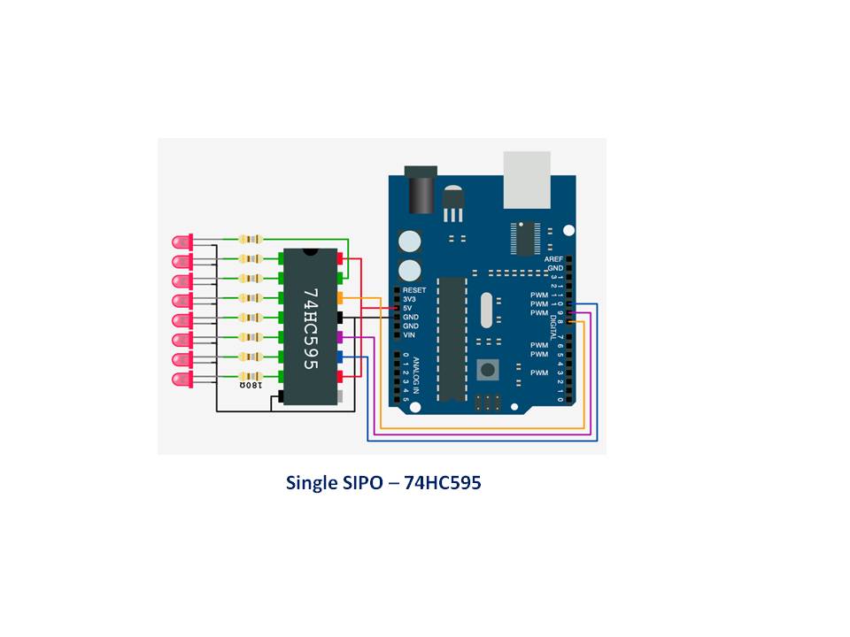
ObjectivesWe shall assume that if you have covered previous tutorials you will already have setup a test harness comprising a single SIPO IC and connected LEDs, but if not and you wish to practise some of the features covered by this tutorial then setup the components as outlined in a previous Tutorial, eg see Tutorial 1, Absolute Addressing.
In this tutorial we shall explore some obvious and less so obvious questions and provide, hopefully, helpful answers.
Q1. What is the virtual array pool of output pins?A1. The SIPO8 library will create and reserve space for every SIPO IC output pin you request when you instantiate the library’s class. This is determined by the first parameter of the class instantiation statement, e.g. SPIO8 my_SIPOs(4, 0), here the request is to create a virtual SIPO output pin environment of 4 x single 8-bit SPIO ICs, or 4 x 8 = 32 output pins.
The entire virtual set of SIPO output pins are referred to as the virtual array or array pool, with an address range from 0 to the (8 x number of SIPO ICs) – 1. In the above example the address range is 0 to 31.
It is important to understand that, once created, the virtual output pin array is not yet addressable. This is because that the library does not yet know how these virtual output pins are to be associated with/linked to the physical world, i.e. physical SIPO ICs. This cannot happen until we allocate the array pool to one or more banks. See question 2.
Q2. How do I link the virtual output pins in the array pool to physical SIPO ICs?Having defined and created our virtual array pool by instantiating the library's class, we now need to 'chop it up'/allocate it into 'banks' of grouped output pins using the create_bank function. A bank will:
- comprise a unique set of virtual output pins allocated from the virtual array pool
- map a consecutive and contiguous absolute address range of virtual output pins into the bank, thereby allowing the these outputs to be addressed relatively to the bank in which they exist - the first output port address of every bank is 0, representing the least significant bit of the bank's SIPO
- define the 3-wire digital microcontroller pins used to drive the bank
- make the bank’s associated output pins active and therefore addressable, absolutely and relatively (see question 3)
For example, using our example above (SPIO8 my_SIPOs(4, 0)), we wish split up our 32 virtual output pins into 2 banks - 1 bank of 8 output pins and the other bank of the remaining 24 output pins, and allocate these to microcontroller digital pins 3, 4, 5 and A0, A1, A2 respectively. The banks are created using the create_bank function so:
bank1_id = my_SIPOs.create_bank(3, 4, 5, 1);    // 8 outputs
bank2_id = my_SIPOs.create_bank(A0, A1, A2, 3); //24 outputs
The first create_bank call allocates array pool pins 0–7 to the first bank (bank1_id) and makes the associated output pins active and addressable (absolutely and relatively). The second create_bank allocates array pool output pins 8–31 to the second bank (bank2_id) and makes the associated output pins active and addressable.
Now the array pool is fully allocated to our banks and all output pins active we can address them in two ways – by absolute addressing and by relative addressing. See question 3.
As an aside, if we tried to call the create_bank function again we would obtain an error, as all instantiation declared SIPOs have been allocated from the array pool - we requested 4 and we allocated 4 (1 + 3).
A3. The answer is very simple:
Absolute addresses relate only to the active output pins in the virtual array pool with an inclusive address range from 0 to (the total number of output pins) - 1 in the array pool. There are few functions (but sufficient) that use absolute addressing, these are:
set_all_array_pins(status)implicit absolute addressing
invert_all_array_pins()implicit absolute addressing
set_array_pin(pin_address)explicit absolute addressing
invert_array_pin(pin_address)explicit absolute addressing
read_array_pin(pin_address)explicit absolute addressing
xfer_array(LSBFIRST_or_MSBFIRST)implicit absolute addressing
where
pin_address is the absolute address of the pin in the active array pool, i.e. an address range from 0 to the (8 x total number of defined and active SIPO ICs) – 1. In the above example, the absolute address range is from 0–31 inclusive. (See the User Guide for a full description of each of these functions.)
Relative addresses relate only to the active output pins in a bank with an inclusive address range from 0 to (the number of output pins in a bank) - 1. There are many bank related functions that use relative addressing, these are:
set_bank_pin(bank_id,pin_address, status)explicit relative addressing
invert_bank_pin(bank_id,pin_address)explicit relative addressing
read_bank_pin(bank_id,pin_address)explicit relative addressing
set_bank(bank_id,status)implicit relative addressing
set_banks(from_bank,to_bank, status)implicit relative addressing
set_banks(status)implicit relative addressing
invert_bank(bank_id)implicit relative addressing
invert_banks(from_bank,to_bank)implicit relative addressing
invert_banks()implicit relative addressing
set_bank_SIPO(bank_id,SIPO_num, SIPO_value)implicit relative addressing
invert_bank_SIPO(bank_id,SIPO_num)implicit relative addressing
read_bank_SIPO(bank_id,SIPO_num)implicit relative addressing
xfer_bank(bank_id,LSBFIRST_or_MSBFIRST)implicit relative addressing
xfer_banks(bank_from,bank_to, LSBFIRST_or_MSBFIRST)implicit relative addressing
xfer_banks(LSBFIRST_or_MSBFIRST)implicit relative addressing
where
pin_address is the relative address of the pin in the bank, i.e. an address range from 0 to (number of output pins in the bank) – 1.
SIPO_num is the relative address of an 8-bit SIPO define by the bank, i.e. ranges from 0 to (number of SIPOs defined for the bank) – 1.
In the above example, the array pool of size 4 x SIPO ICs is split into two separate banks, one bank with 1 x SIPO IC and the other with 3 x SIPO ICs, the respective addressing ranges are:
array pool, absolute address range: 0–31
bank1_id relative address output pin range: 0-7, relative SIPO byte range: 0-0
bank2_id relative address output pin range:0–23, relative SIPO byte range: 0-2
(See the User Guide for a full description of each of these functions.)
Q4.How do I know how many virtual SIPO output pins there are in the array pool?A4. The library provides a number of user accessible variables that are helpful in decision support and control. In this particular case, the library variable to use is max_pins*,and you would use it by prefixing it with the name you gave for the SIPO8 class when you instantiated it. For example, if you named your class ‘my_SIPOs’ then the use would be my_SIPOs.max_pins.
Be aware that this value is the total number of output pins defined at library class instantiation - it is not the number of active output pins, see question 5.
Q5. How do I know how many virtual active output SIPO pins there are in the array pool?A5. Again, we would use a library variable, in this instance the library variable num_active_pins*, and you would use it by prefixing it with the name you gave for the SIPO8 class when you instantiated it. For example, my_SIPOs.num_active_pins.
* Note that there is a distinction to be made between how many SIPO pins an array pool is sized for (max_pins) and the number of active pins (num_active_pins) in an array. When the SIPO8 class is instantiated, the array pin pool is created to be as large as required by the provided respective class parameter. However, at this point none of the array pins are accessible. Before they can be used/accessed they need to be assigned into banks using the create_bank function, which groups contiguous pins into groups of a multiple of eight output pins. (See question 1).
A6. The library has a function specifically for this need – get_bank_from_pin. It takes a single parameter (absolute pin address) and returns the id of the bank it is mapped by. If the specified pin does not belong to any bank then it will return a value of -1 (reserved macro name of 'bank_not_found'). Look at the following example which shows how we can work from an absolute active pin address to its associated bank and then draw together a number of useful attributes:
int bank_id = my_SIPOs.get_bank_from_pin(97);
if (bank_id != bank_not_found){
  // ok, work on this bank
  uint16_t low_pin_add = SIPO_banks[bank_id].bank_low_pin;
  uint16_t high_pin_add = SIPO_banks[bank_id].bank_high_pin;
  uint8_t num_SIPOs = SIPO_banks[bank_id].bank_num_SIPOs;
  // we now have number of SIPOs in this bank and the
  // absolute pin address range of all pins in the bank
  ...
}
A7. Central to the library’s design is a control struct(ure) called SIPO_banks (you saw an example of this in question 6). It is fully documented in the User Guide, but for convenience it looks like:
struct SIPO_control {
uint8_t bank_data_pin;
uint8_t bank_clock_pin;
uint8_t bank_latch_pin;
uint8_t bank_num_SIPOs;
uint16_t bank_low_pin;
uint16_t bank_high_pin;
} *SIPO_banks;
For a given bank id, any of the its bank attributes may be accessed/referenced simply by giving the bank_id, for example:
unit16_t abs_start = my_SIPOs.SIPO_banks[bank_id].bank_low_pin;
unit16_t abs_last  = my_SIPOs.SIPO_banks[bank_id].bank_high_pin;
and, if we wished to find out how many output pins a bank owns/maps, we can do this in several way:
1.
uint8_t num_pins = my_SIPOs.SIPO_banks[bank_id].bank_high_pin–
my_SIPOs.SIPO_banks[bank_id].bank_low_pin + 1;
2.
uint8_t num_pins = my_SIPOs.SIPO_banks[bank_id].bank_num_SIPOs
* pins_per_SIPO;
'pins_per_SIPO' is a library reserved word.
3. or, directly, using a specific function...
uint8_t num_pins = my_SIPOs.num_pins_in_bank(bank_id);
Note that, although bank pin addressing is relative addressing, the low/high pin addresses held in a bank are absolute pin address values.
Q8. What other things should I know about that may be useful?A8. A bit of an open question, but let’s look at what other library variables are accessible and which you may find helpful. The list below highlights several of these, but more precise information can be found in the User Guide.
Other user accessible SIPO8 library variables you may find helpful are:
Virtual Map Array: uint8_t * pin_status_bytes
Every virtual, and therefore every physical, SIPO output pin is mapped by a single bit in the pin_status_bytes array. This array is sized sufficient to map all required SIPO output pins, starting at pin 0. Each 8-bit byte of the array corresponds to 8 output pins. Therefore byte 0 holds output pins 0 – 7, byte 1 holds output pins 8 – 15, and so on. It may be accessed directly, for example:
status_byte = pin_address / pins_per_sipo;
status_pin = pin_address % pins_per_sipo;
pin_status =  bitRead(pin_status_bytes[status_byte],status_pin);
Much better to use the library’s explicit functions?
Number of Virtual Map Array Status Bytes: my_SIPOs.num_pin_status_bytes
This variable provides the total number of pin status bytes mapping the entire array pool. For example:
// clear down all status byte pins
uint8_t num_bytes, byt;
num_bytes = my_SIPOs.num_pin_status_bytes;
for(byt = 0; byt < num_bytes; byt++){
     pin_status_bytes[byt] = 0;
}
Number of Active SIPO Banks: my_SIPOs.num_banks
This variable defines the total number of banks created using the create_bank function. For example, as banks start at bank 0 and run consecutively:
uint8_t num_banks, bank;
num_banks = my_SIPOs.num_banks;
for(bank = 0; bank < num_banks; bank++){
   my_SIPOs.xfer_bank(bank,LSBFIRST_or_MSBFIRST);
}
The above code is equivalent to any one of the following:
my_SIPOs.xfer_banks(LSBFIRST_or_MSBFIRST);
my_SIPOs.xfer_banks(0, my_SIPOs.num_banks-1,LSBFIRST_or_MSBFIRST);
my_SIPOs.xfer_array(LSBFIRST_or_MSBFIRST);
Total Instantiated SIPO ICs: my_SIPOs.max_SIPOs
This is the number of 8-bit SIPOs the SIPO8 class was instantiated for.
For example: SPIO8 my_SIPOs(4, 0);
Here my_SIPOs.max_SIPOs would be equal to 4.
Number SIPO ICs Allocated: my_SIPOs.bank_SIPO_count
The total number of 8-bit SIPOs allocated to banks.
Until all SIPOs have been allocated to a bank then:
my_SIPOs.bank_SIPO_count < my_SIPOs.max_SIPOs
When all class defined SIPOs are allocated to banks then:
my_SIPOs.bank_SIPO_count == my_SIPOs.max_SIPOs
Maximum Number of SIPO Timers: my_SIPOs.max_timers
The number of SIPO8 timers that class has been instantiated for. Note that this value can be 0 to 255.
Timer Control Structure
Every timer created at class instantiation is allocated its own timer control entry in the timer_control structure which is defined as below:
struct timer_control {
  bool timer_status;
  uint32_t start_time;
} *timers;
This structure is used to control each of the defined timers with each timer entry being referenced by the timer_number, from 0 to my_SIPOs.max_timers -1. For example:
if (my_SIPOs.timers[3].timer_status==active){
  ...
}
This tutorial will finish with a couple of sketches that are designed to provide further demonstrations of use of the ez_SIPO8_lib:
1. a sketch to chase the seconds around a clock face, and
2. a sketch to monitor the status of six toggle switches and to display their status (on or off), plus a heart beat monitor.
Sketch Example – Clock Chasing Second LEDsIn this sketch we demonstrate a chasing LED effect to represent the passing of each second on a clock face, with one LED representing one second. Hence the sketch will be designed with eight 8-bit SIPO ICs, giving a total of 64 output pins, although we will limit the sketch to the first 60 of these (0-59). Each LED will be illuminated for each passing second until all 60 have been lit (one minute), after which all LEDs will be extinguished and the cycle restarted.
Although the sketch is initially designed as a clock second chaser, it may be adjusted for the number of LEDs chased (up to 64 without adding more SIPO ICs) and the frequency at which LED illumination occurs. To make these changes vary the macro definitions:
1. ‘#define chase_length’ – set this from 0 – 64 output pins
2. ‘#define frequency’ – set this to be the frequency at which LED illumination is to occur.
Note that this example uses absolute addressing functions.
The SIPO configuration parameters are as below:
If you are going to recreate this project then you will need to connect together (cascade) eight x 8-bit SIPO ICs and link all outputs apart from the last four of the last SIPO IC to LEDS; see Tutorial 4, Cascading SIPOs). It may also be worthwhile considering adding in external power to power up the SIPO cascade.
Download the sketch from the Code section.
The global SIPO8 data for this sketch are:
SIPO
pins_per_SIPO = 8
max_SIPOs = 8
bank_SIPO_count= 8
num_active_pins= 64
num_pin_status_bytes= 8
next_freebank = all SIPOs used
Numbertimers = 1
Bankdata:
bank= 0
  num SIPOs = 8
  latch_pin = 9 clock_pin = 10 data_pin = 8
  low_pin = 0 high_pin = 63
I do have to make a bit of an admission - I have not physically made this project - I couldn't face all those connections! So if you do and it does what it supposed to do then please drop me a line. I did, of course, test the code 'on the bench' , so to speak, and it seemed to do what it was supposed to do!
Example Sketch - Switch Status DisplaysIn this sketch we use a single 8-bit SIPO IC and assign output ports (0-5) each to a dummy toggle switch so that their statuses are shown on connected LEDs - LED on (HIGH) if the switch is on, LED off (LOW) otherwise.
Note that the sketch does not use real or physically connected toggle switches but, instead, introduces a function to provide feedback for a given switch as to whether it is in an on or off state. The function will randomly decide if the given switch is to be switched into its opposite state. These states are then used to update the bank created for the SIPO IC to which the dummy toggle switches are linked.
In addition, output port 7 is used to drive a heart beat monitor to show the sketch is running.
The sketch uses the same single SIPO test harness and 3WI we have used throughout these tutorials. Down load the sketch, compile and upload to see the randomly changing toggle switch status conditions plus the heart beat monitor.
To note is:
- SIPO IC output ports 0-5 have LEDs connected to display the status of their respective toggle switches (dummy switches)
- SIPO IC output port 6 is not used
- SIPO IC output port 7 is used as the heart beat monitor to show that the sketch is running
- we use library functions we have already seen, plus two new ones -
invert_bank_pin(bank_id, pin_number)andread_bank_pin(bank_id, pin_number), wherepin_numberis a relative bank output port address in the range 0-7 (6 not used)
- we use the library's timer functions for testing the switches and for the heart beat monitor.
The global SIPO8 data for this sketch are:
SIPO
pins_per_SIPO = 8
max_SIPOs = 1
bank_SIPO_count= 1
num_active_pins= 8
num_pin_status_bytes= 1
next_freebank = all SIPOs used
Numbertimers = 1
Bankdata:
bank= 0
  num SIPOs = 1
  latch_pin = 9 clock_pin = 10 data_pin = 8
  low_pin = 0 high_pin = 7
That is the end of this tutorial which I trust you have found to be helpful?
I hope that you have found these tutorials useful and that you have seen a variety of uses to which the ez_SIPO8_lib library may be put and that you are able to make good use of it in your projects.
A copy of this Q&A tutorial can be downloaded from github here.
If you wish to link to the tutorial starting article then follow this link: Tutorial Start.

Comments
Please log in or sign up to comment.