


Hardware components | ||||||
_ztBMuBhMHo.jpg?auto=compress%2Cformat&w=48&h=48&fit=fill&bg=ffffff) |
| × | 1 | |||
 |
| × | 7 | |||
 |
| × | 7 | |||
 |
| × | 1 | |||
 |
| × | 8 | |||
 |
| × | 1 | |||
 |
| × | 1 | |||
Software apps and online services | ||||||
 |
| |||||
I recently put together a simple roll the die sketch for my grandson to use whilst playing his board games. He was very happy with the result, but I thought it might be instructive for others to share the 'roll the dice' sketch and to also provide an alternative version to throw two dice (see the Rolling the Dice, part 2 article).
In this article, I offer part 1 of two 'roll the dice' sketches - the rolling of a single die. The design of the part 1 die sketch and components is straight forward – it uses 7 x LEDs to represent each of the standard pip patterns found on each of the six faces/sides of a standard die and a single simply connected button switch.
If you are wondering why seven and not six LEDs are used, it is because seven LEDs are required to mirror all possible layout combinations of all sides of a traditional standard die (see below). Each of the seven LEDs is mapped and connected to a microcontroller digital IO port. For a single die, this is okay, but if we start thinking about adding two or more dice then no, too many microcontroller ports would be required. But not to worry, this is where the 'Rolling the Dice, part 2' article picks up the pace and shows how we can achieve this using low cost serial-parallel input/output ICs, e.g. 74HC595 ICs, to add as many dice as we want. However, for this part 1 article, we make a start by connecting one die and its LEDs directly to the microcontroller. Let's get going at looking at this part 1 article...
Design - HardwareLEDs
As mentioned above, the circuit design features 7 x LEDs and one x button switch. Seven LEDs are used in this design such that we are able to lay these out into a physical arrangement on our breadboard that reflects the pip (spot) layout of each face/side of a traditional six sided die, so:
The breadboard arrangement I eventually ended up with was:
I decided to use different coloured LEDs just to add a bit more interest, but any colours will do. I apologise for the different coloured short jumper wires as my choice from my jumper kit was limited. To note is that these jumpers connect to each LED positive terminal and thence to the microcontroller connecting wires further along the breadboard. Without these jumpers the LEDs become cluttered with wires so a little patience to wire up the board is rewarded.
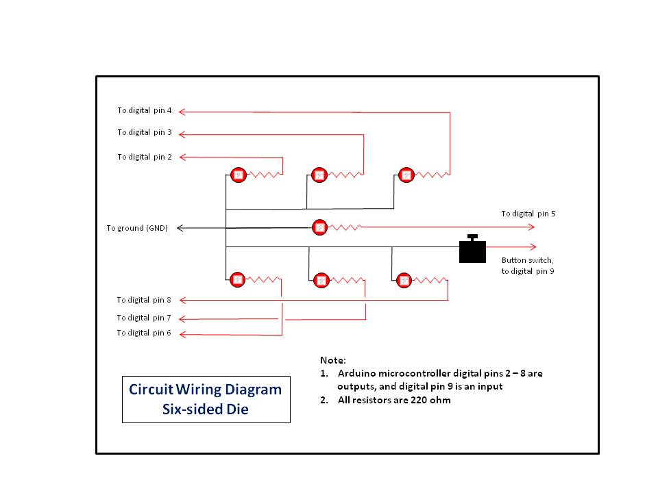
For reference, the LED to microcontroller digital pin assignments are as follows (note that the orientation of the LEDs on the breadboard are as per image above):
- bottom right (red) LED - digital pin 2
- bottom middle (green) LED - digital pin 3
- bottom left (blue) LED - digital pin 4
- middle (yellow) LED - digital pin 5
- top right (red) LED - digital pin 6
- top middle (green) LED - digital pin 7
- to left (blue) LED - digital pin 8
- and finally, the button switch is connected to digital pin 9
Button Switch
A single button switch is used in the design such that when pressed and released a new throw of the die is actioned. The sketch uses the ez_switch_lib library which simplifies design. The ez_switch_lib instance is initialised for a single switch and further defined in setup (the add_switch function) to be a button switch simply connected without a pull down resistor. Note that the parameters of the add_switch function include two library macros - 'button_switch' and 'circuit_C2'. These are defined in the ez_switch_lib header file (.h) so just need to be referenced.
Once the library is declared, the instance created and the button switch added/created then all that is required is to constantly test the status of the switch which is done in the main loop. If the button switch is pressed and released then a status of 'switched' is returned (also a defined macro of the ez_switch_lib library).
The button switch may be located anywhere on the breadboard were convenient and wired in accordance with the schematics. I managed to squeeze it on the left hand side edge which gave easy access. See the Schematics for diagram of the layout of components.
Design - SketchBefore explaining the central part of the sketch, I should mention that I have included within it a heart beat monitor which is designed to flash the in-built microcontroller LED (LED_BUILTIN, usually on pin 13) at a frequency of 1 hertz (1 cycle per second). This provides some physical indication that the sketch is running (or not). If this aspect of the sketch is not required then it may be disabled by setting a macro definition in the heart beat declaration section to 'false'. That is, set '#define heart_beat_on false'. The associated data for the heart beat monitor is:
// Define heart beat data...
//
#define heart_beat_pin   LED_BUILTIN  // digital pin for heart beat LED
#define heart_beat_on    true         // determines if the implementation uses the heartbeat
long unsigned heart_beat_freq = 1000; // time(milliseconds) of heart beat frequency
long unsigned heart_beat_on_off_time; // the time the LED is on and off - 1/2 frequency
long unsigned last_heart_beat_time;   // time in milliseconds of last heart beat status change
bool heart_beat_status = HIGH;        // current status of heart beat, start high
I have already mentioned that the code uses the on-board LED (LEDBUILTIN) and how to disable the monitor if not required, but if you wish to vary the frequency of the monitor then edit the variable 'heart_beat_freq' to be the total number of cycles per second wished. Note that a complete cycle is on and then off, so the flash rate is automatically calculated to be 1/2 the selected frequency.
The heart_beat function is straight forward but the heart beat will only operate if the function is regularly called. It should therefore be called throughout the code as can be seen in the sketch.
Moving on, the sketch operates by monitoring if the connected button switch has been pressed or not. The button switch is configured using the ez_switch_lib library which removes from the sketch design any hassles with debounce. To access the ez_switch_lib Project Hub article and download the library files follow this link - ez_switch_lib.
To incorporate the library, create a directory under your local Arduino/libraries directory called 'ez_switch_lib' and download the three files into this directory from the Project Hub article:
1. ez_switch_lib.h
2. ez_switch_lib.cpp
3. keywords.txt
Now let's look at the other principal parts of the sketch:
Library DeclarationandInitiation
The switch library is declared as follows:
#include <ez_switch_lib.h>
and is initiated with for a single switch by:
Switches my_switches(1);
Here we have created a switch instance to be sized for just one switch and use 'my_switches' as its instance name. We do not define its type just yet (see setup).
setup - The setup function initialises everything needed by the sketch:
- we set up of the button switch using the
add_switch()function. This has three parameters - switch type, switch pin and circuit type, where switch type is defined by the library reserved macro 'button_switch', switch pin is defined as 'button_switch_pin', the digital pin (12) we have decided to use in our sketch, and circuit type which is defined by the library reserved macro 'circuit_C2'. This informs the switch library that the switch is to be wired simply without a 10k ohm pulldown resistor.
- the declared LEDs and
- the heart beat monitor
To note is that the assignment process for the button switch is verified for success. If the switch cannot be assigned, for any reason, then the sketch will terminate. This will be seen if the heart beat monitor has been configured and it is observed not to be operating (flashing). The value of the 'button_switch_pin' parameter is as defined by the sketch macro.
announce_throw - this function is called between throws of the die (on press of the button switch) and displays a short strobe pattern of the die to indicate a throw is about to start.
The function performs two strobe cycles illuminating each LED defined by digital ports mapped to the LEDs. The pattern is arbitrary and may be configured to to anything desired.
void announce_throw() {
 uint8_t led;
 // Start by clearing down the existing die pips/score
 clear_pips();
 for (uint8_t cycle = 1; cycle <= 2; cycle++) {// do 2 cycles
   for (uint8_t led = 0; led < max_leds; led++) {
     digitalWrite(pip_pins[led], HIGH);
     digitalWrite(pip_pins[max_leds - led - 1], HIGH);
     delay(60);
     heart_beat(); // keep pumping the heart beat timer whilst doing the announcing the throw
     digitalWrite(pip_pins[led], LOW);
     digitalWrite(pip_pins[max_leds - led - 1], LOW);
     delay(20);
     heart_beat(); // keep pumping the heart beat timer whilst doing the announcing the throw
   }
 }
}
throw the die - The throw_die() function firstly 'announces' that a throw of the die is about to start by strobing each of the seven LEDs on/off over two cycles by calling the announce_throw() function.
After this, the function resets the random seed at each call and then determines a throw value (a random face/side of the die) in the range 0-5 (or 1-6 in the real world).
Using this value, the function then examines if a LED is defined for each pip of that face and, if so, illuminates the associate LED.
...
#define faces_per_die      6
#define max_pips_per_face  6
uint8_t pip_patterns[faces_per_die][max_pips_per_face] = {
// LEDs that represent die pip patterns, faces/side 1-6 (array index 0-5) across 7 leds
 5, 0, 0, 0, 0, 0, // 1 pip, just the central LED
 3, 7, 0, 0, 0, 0, // 2 pips, each central two outer LEDs
 2, 5, 8, 0, 0, 0, // 3 pips, diagonal LEDs
 2, 4, 6, 8, 0, 0, // 4 pips, each corner LED
 2, 4, 5, 6, 8, 0, // 5 pips, all LEDs
 2, 3, 4, 6, 7, 8, // 6 pips, each outer column of 3 LEDs
};
...
void throw_die() {
  announce_throw();   // 'announce' the throw of the die
  randomSeed(analogRead(A0) * 31 +
            analogRead(A1) * 37 +
            random(1023, 10000)); // keep changing the seed
  uint8_t die_face = (random(1, 104640) % faces_per_die); // range 0-(faces_per_die-1)
  // Now display the pips on the die
  for (uint8_t column = 0; column < max_pips_per_face; column++) {
    uint8_t led = pip_patterns[die_face][column];
    if (led != 0) {
      // A pip LED is defined so illuminate it
      digitalWrite(led, HIGH);
    }
  }
}
main loop - The main loop of the sketch is very simple and continually cycles checking the status of the button switch using the read_switch function (myswitches.read_switch(switch_id)). Only if a press/release cycle is detected (switch read function returns a value of 'switched') will a throw of the die be actioned by calling the throw_die() function:
void loop() {
 do {
   heart_beat(); // keep pumping the heart beat timer every cycle
   if (my_switches.read_switch(switch_id) == switched) {
     // the value 'switched' is defined by ez_switch_lib.h
     // Switch has been pressed and released, so throw the die...
     throw_die();
   }
 } while (true);
}
That's it, I hope you have some fun using it in your board games, but if you want to use more than one die then why not explore the part 2 article which offers an alternative method for connecting two or more dice.


Comments
Please log in or sign up to comment.