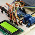
In this tutorial we are going to use an RFID reader that will display a Tag ID on the OLED Display. To achieve this we are going to use the existing Arduino code & library that I found on the internet.
Custom Code component in Visuino Pro is very useful if you need to add some sensor that is not yet supported in Visuino but you already have the code for it, or to just experimenting by adding your own code to the project.
More about Visuino Pro here
Here are also some very good tutorials on how to use a Custom Code component:
Getting started with the Custom Code component
Step 1: What You Will Need- RFID module MFRC522
- Some RFID card for the test
- OLED Display
- Arduino UNO
- Jumper wires
- Breadboard
- Visuino Pro software: Download here
- Connect RFID module pin[SDA] to Arduino digital pin[10]
- Connect RFID module pin[SCK] to Arduino digital pin[13]
- Connect RFID module pin[MOSI] to Arduino digital pin[11]
- Connect RFID module pin[MISO] to Arduino digital pin[12]
- Connect RFID module pin[GND] to Arduino pin[GND]
- Connect RFID module pin[RST] to Arduino digital pin[9]
- Connect RFID module pin[3.3v] to Arduino pin[3.3v]
Go to https://miliohm.com/ and download
Extract this two files to your Arduino Libraries folder, usually it looks something like this: C:\Users\User\Documents\Arduino\libraries
You can also find the Path if you in Visuino click on the Menu>Arduino>Configure and see it under "Arduino Library Directory" (see attached screenshot)
We are also going to use and modify this code from the :https://miliohm.com/
#include <SPI.h>
#include <RFID.h>
#define SS_PIN 10
#define RST_PIN 9
RFID rfid(SS_PIN, RST_PIN);

String rfidCard;

void setup() {
  Serial.begin(9600);
  Serial.println("Starting the RFID Reader...");
  SPI.begin();
  rfid.init();
}

void loop() {
  if (rfid.isCard()) {
    if (rfid.readCardSerial()) {
      rfidCard = String(rfid.serNum[0]) + " " + String(rfid.serNum[1]) + " " + String(rfid.serNum[2]) + " " + String(rfid.serNum[3]);
      Serial.println(rfidCard);
    }
    rfid.halt();
  }
}
The Visuino Pro: https://www.visuino.eu also needs to be installed. Download Free version or register for a Free Trial.
Start Visuino as shown in the first picture Click on the "Tools" button on the Arduino component (Picture 1) in Visuino When the dialog appears, select "Arduino UNO" as shown on Picture 2
Step 5: In Visuino Add Components- Add "Custom Code" component
- Add "OLED I2C" component
- Add "Clock Generator" component
- Double click on the "CustomCode1" and in the "Outputs" window drag "Text" to the left side and close the "Outputs" window
- Double click on the "DisplayOLED1" and in the "Elements" window drag "Draw text" to the left side & in the properties window set "Size" to 2 and "Text" to: Serial #
- In the "Elements" window also drag "Text Field" to the left side & in the properties window set "Size" to 2 and "Y" to 30
- Close the "Elements" window
Select "CustomCode1" and in the properties window select "Defines" and Click on the 3dots button
In the "Defines" window add this code:
#define SS_PIN 10
#define RST_PIN 9
And Close the "Defines" window
Select "CustomCode1" and in the properties window select "Globals" and Click on the 3dots button
In the "Globals" window add this code:
RFID rfid(SS_PIN, RST_PIN);And Close the "Globals" window
Select "CustomCode1" and in the properties window select "Includes" and Click on the 3dots button
In the "Includes" window add this code:
#include <SPI.h>
#include <RFID.h>
And Close the "Globals" window
Select "CustomCode1" and in the properties window select "On Execute" and Click on the 3dots button
In the "On Execute" window add this code:
{


    if (rfid.isCard()) {
    if (rfid.readCardSerial()) {
      Text1.Send(String(rfid.serNum[0]) + " " + String(rfid.serNum[1]) + " " + String(rfid.serNum[2]) + " " + String(rfid.serNum[3]));

    }
    rfid.halt();
  }

}
And Close the "On Execute" window
Select "CustomCode1" and in the properties window select "On Init" and Click on the 3dots button
In the "On Init" window add this code:
SPI.begin();
 rfid.init();
And Close the "On Init" window
Step 8: In Visuino Connect Components- Connect "ClockGenerator1" pin [Out] to "CustomCode1" pin [Clock]
- Connect "CustomCode1" > "Text1" pin [Out] to "DisplayOLED1" > "Text Field1" pin [In]
- Connect "DisplayOLED1" pin Out [I2C] to "Arduino" pin In [I2C]
In Visuino, at the bottom click on the "Build" Tab, make sure the correct port is selected, then click on the "Compile/Build and Upload" button.
Step 10: PlayIf you power the Arduino board and place the RFID Card on the RFID module the OLED Display will show the Tag ID.
Congratulations! You have completed your project with Visuino. Also attached is the Visuino project, that I created for this Instructable, you can download it and open it in Visuino: https://www.visuino.eu


_ztBMuBhMHo.jpg?auto=compress%2Cformat&w=48&h=48&fit=fill&bg=ffffff)


Comments
Please log in or sign up to comment.