


Hardware components | ||||||
 |
| × | 1 | |||
Software apps and online services | ||||||
 |
| |||||
Have you ever wanted a nice cold brew but were too comfy on the couch to get up and grab one yourself? Is your wife/husband too callous, your children too lazy, or your dog too stupid to fetch it for you? With the new BeerBot 1000, you will never have this problem again! Simply command the BeerBot and an ice cold beer will be delivered to you! See in the video below:
As of this writing, there are no other commercially available electronic assistant that can retrieve users an ice cold can of beer. See below an Amazon Alexa, a supposed "gold standard of home automation" attempting to deliver a beer:
Not only will the BeerBot 1000 deliver you your delicious beverage in a timely manner, it can also sing you Escape (The Piña Colada Song) by Rupert Holmes! However, when you've had too many drinks (15 deliveries), the bot becomes inoperable as adult beverages should be consumed responsibly.
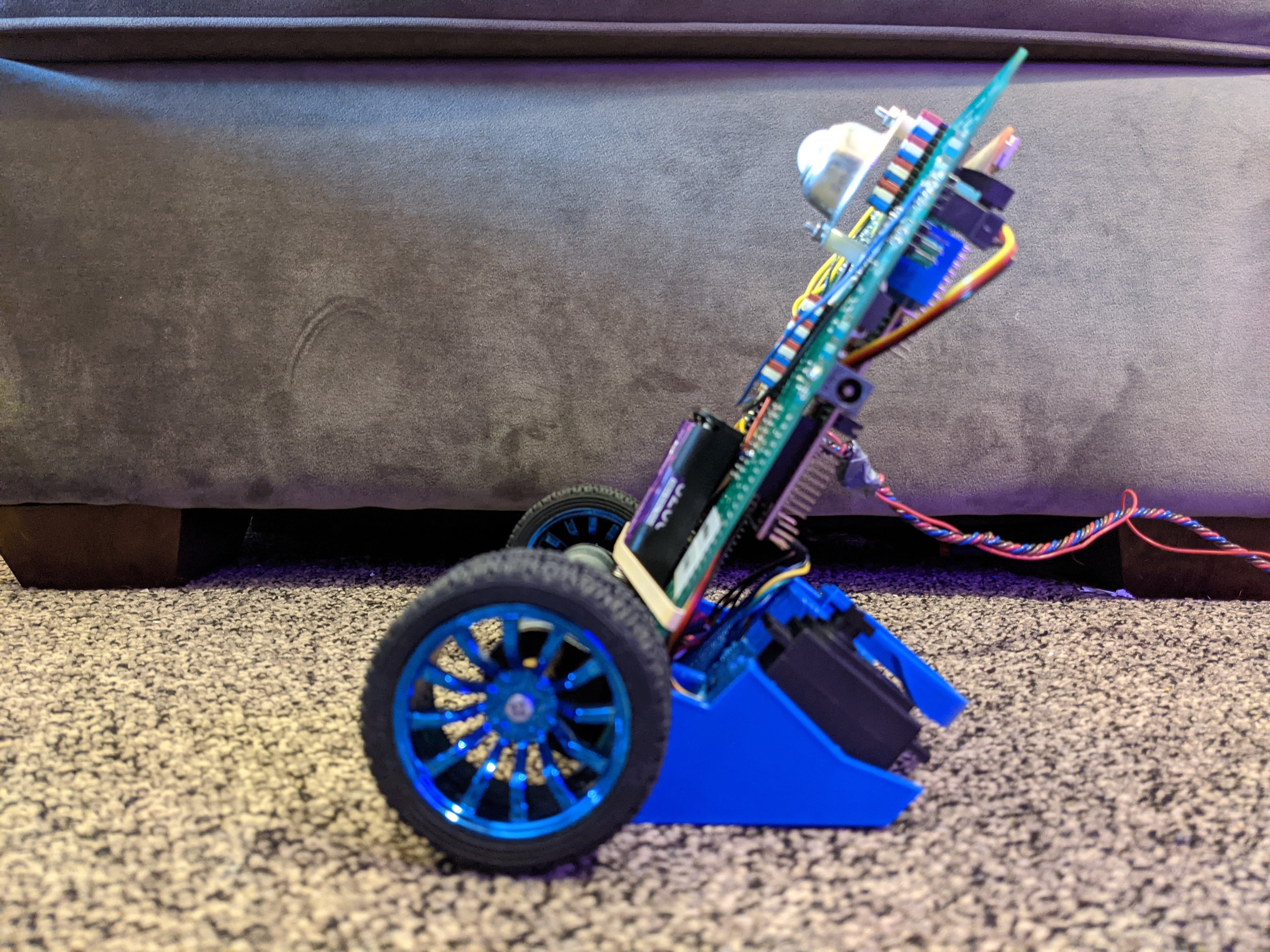
How does it work?You may wonder, how does the BeerBot 1000 work? Is such magic even possible? Yes, it is! The heart of BeerBot is the green ME 461 PCB. Connected to it is the brain of the system, the Texas Instruments F28379D Launchpad, a low cost evaluation and development tool for the TI F2837xD, F2837xS, and F2807x series. Additionally, an HS 311 Servo powers the claw that grips the beer. An MPU 9250 chip provides gyroscopic and acceleration data, which is used for balancing. Lastly, a set of motors allows the BeerBot to move itself around. A brief video identifying these components is shown below.
The HS 311 Servo is positioned using an PWM signal. The signal sets the servo, and by extension, the arm, to two position. Whether the arm is set open or closed depends on whether the joystick is pressed. The state of the joystick button is monitored using GPIO 123 on the green board. The buzzer, which plays the music, is also controlled via PWM. A timer interrupt triggers each note, and the frequency of the note is determined by the duty cycle of the PWM signal. Due to how fast the timer interrupt occurs, notes can be played very quickly. Each quarter note in Escape is actually subdivided into 6 separate tones!
Frequently Asked Questions1. Does the BeerBot work with sodas?
Unfortunately, as of present, the BeerBot 1000 is not capable of delivering sodas. It is only rated for brown ales, pale ales, india pale ales, golden ales, scotch ales, barley wines, mild, ales, burton ales, old ales, belgian ales, cask ales, helles, pilsners, marzens, bocks, vienna lagers, dunkels, schwarzbiers, and American pale ales. A future software update may allow for deliveries of hard seltzers, but for your pop delivery needs, stay tuned for the release of the upcoming SodaServant 600!
2. How much does the BeerBot 1000 cost?
The BeerBot 1000 is not yet commercially available. Even though the Texas Instruments F28379D Launchpad is extremely inexpensive, the proprietary "green board" is intellectual property of Professor Dan Block's ME 461 Computer Control of Mechanical Systems. Tuition at the University of Illinois at Urbana-Champaign ranges anywhere from $7,561 to $16,132+. However, the knowledge you learn building a BeerBot 1000 is priceless so the price is incredibly difficult to gauge.
3. Hmm. The TI F28379D Launchpad development kit seems pretty great! I can see myself using that in one of my own projects- can I buy it anywhere?
Yes and yes! It is pretty great, and you can find out more about it here.
4. How advanced is the BeerBot 1000's navigation algorithm?
The BeerBot 1000 actually must be controlled via joystick. As of now, it does not possess any navigation or collision avoidance features. However, using its accelerometer, gyroscope, and wheel speed data, the BeerBot 1000 can balance itself on only two wheels!
5. Who designed and built the BeerBot 1000?
The "heart" of the BeerBot 1000, the green board, was designed by Professor Dan Block, instructor of ME 461 at the University of Illinois and the "brain" was developed by Texas Instruments. Much of the software was written by Dr. Dan Block, and the rest was completed by Ryan Siu, a Senior in Mechanical Engineering at U of I. The claw and modified feet were also designed by Ryan. In his free time, Ryan enjoys cycling, hiking, and of course, drinking beer. Lastly, much thanks go to Hang and Chad, the TAs of ME 461 who were also key contributors to this project.
//#############################################################################
//                                                                           //
//                   Ryan's Dope BeerBot                                     //
//                                                                           //
//#############################################################################

// Included Files
#include <stdio.h>
#include <stdlib.h>
#include <stdarg.h>
#include <string.h>
#include <math.h>
#include <limits.h>
#include "F28x_Project.h"
#include "driverlib.h"
#include "device.h"
#include "f28379dSerial.h"

#define PI          3.1415926535897932384626433832795
#define TWOPI       6.283185307179586476925286766559
#define HALFPI      1.5707963267948966192313216916398


// Interrupt Service Routines predefinition
__interrupt void cpu_timer0_isr(void);
__interrupt void cpu_timer1_isr(void);
__interrupt void cpu_timer2_isr(void);
__interrupt void ADCA_ISR (void); //ADCB Interrupt Function for Joystick
__interrupt void SPIB_isr(void); //Lab 4 Ex 4 Stuff
__interrupt void SWI_isr(void);
void setupSpib(void);
void serialRXA(serial_t *s, char data);

//Predefinitions for the 3 motor functions (11/05/20)
void init_eQEPs(void);
float readEncLeft(void);
float readEncRight(void);
void setEPWM6A(float controleffort); //Copied from Lab 2
void setEPWM6B(float controleffort);


// Variables/Definitions for Final Project
#define sizefilter 10 //For joystick filtering
//Notes and their corresponding carrier frequencies
//(Pitched up an octave because the buzzer can't play low enough notes)
#define C4 (50000000.0 / (261.63 * 4))
#define Db4 (50000000.0 / (277.18 * 4))
#define D4 (50000000.0 / (293.66 * 4))
#define Eb4 (50000000.0 / (311.13 * 4))
#define E4 (50000000.0 / (329.63 * 4))
#define F4 (50000000.0 / (349.23 * 4))
#define Gb4 (50000000.0 / (369.99 * 4))
#define G4 (50000000.0 / (392.00 * 4))
#define Ab4 (50000000.0 / (415.30 * 4))
#define A4 (50000000.0 / (440.00 * 4))
#define Bb4 (50000000.0 / (466.16 * 4))
#define B4 (50000000.0 / (493.88 * 4))
#define C5 (50000000.0 / (523.25  * 4))
#define Db5 (50000000.0 / (554.36 * 4))
#define D5 (50000000.0 / (587.32 * 4))
#define Eb5 (50000000.0 / (622.26 * 4))
#define E5 (50000000.0 / (659.26 * 4))
#define F5 (50000000.0 / (698.46 * 4))
#define G5 (50000000.0 / (783.99 * 4))
#define Ab5 (50000000.0 / (830.61 * 4))
#define A5 (50000000.0 / (880.00 * 4))


#define songsize    768
//#define songsize 1
//24 "notes" per measure (quarter gets 6
float song[songsize]={//Bar 8
                      0.0, 0.0, 0.0, 0.0, 0.0, 0.0, A4, A4, 0.0, A4, A4, 0.0, A4, A4, 0.0, A4, A4, 0.0, A4, A4, 0.0, G4, G4, 0.0,
                      A4, A4, A4, A4, A4, 0.0, C5, C5, C5, C5, C5, 0.0, 0.0, 0.0, 0.0, 0.0, 0.0, 0.0, 0.0, 0.0, 0.0, 0.0, 0.0, 0.0,
                      0.0, 0.0, 0.0, A4, A4, 0.0, A4, A4, 0.0, G4, G4, 0.0, A4, A4, 0.0, A4, A4, 0.0, G4, G4, G4, G4, G4, G4,
                      C4, C4, C4, 0.0, 0.0, 0.0, 0.0, 0.0, 0.0, 0.0, 0.0, 0.0, 0.0, 0.0, 0.0, 0.0, 0.0, 0.0, 0.0, 0.0, 0.0, 0.0, 0.0,
                      //Bar 12
                      0.0, 0.0, 0.0, 0.0, 0.0, 0.0, A4, A4, 0.0, A4, A4, 0.0, A4, A4, A4, A4, A4, 0.0, A4, A4, 0.0, G4, G4, 0.0,
                      A4, A4, A4, A4, A4, 0.0, C5, C5, C5, C5, C5, 0.0, 0.0, 0.0, 0.0, 0.0, 0.0, 0.0, 0.0, 0.0, 0.0, 0.0, 0.0, 0.0,
                      0.0, 0.0, 0.0, 0.0, 0.0, 0.0, A4, A4, 0.0, G4, G4, 0.0, A4, A4, 0.0, A4, A4, 0.0, G4, G4, G4, G4, G4, G4,
                      C4, C4, C4, 0.0, 0.0, 0.0, 0.0, 0.0, 0.0, 0.0, 0.0, 0.0, 0.0, 0.0, 0.0, 0.0, 0.0, 0.0, 0.0, 0.0, 0.0, 0.0, 0.0,
                      //Bar 16
                      0.0, 0.0, 0.0, A4, A4, 0.0, A4, A4, 0.0, A4, A4, 0.0, A4, A4, A4, A4, A4, 0.0, G4, G4, G4, G4, G4, 0.0,
                      A4, A4, A4, A4, A4, 0.0, C5, C5, C5, C5, C5, 0.0, 0.0, 0.0, 0.0, 0.0, 0.0, 0.0, 0.0, 0.0, 0.0, 0.0, 0.0, 0.0,
                      0.0, 0.0, 0.0, A4, A4, 0.0, A4, A4, 0.0, G4, G4, 0.0, A4, A4, 0.0, A4, A4, 0.0, G4, G4, G4, G4, G4, G4,
                      C4, C4, C4, 0.0, 0.0, 0.0, 0.0, 0.0, 0.0, 0.0, 0.0, 0.0, 0.0, 0.0, 0.0, 0.0, 0.0, 0.0, 0.0, 0.0, 0.0, 0.0, 0.0,
                      //Bar 20
                      0.0, 0.0, 0.0, 0.0, 0.0, 0.0, A4, A4, 0.0, A4, A4, 0.0, A4, A4, 0.0, A4, A4, 0.0, A4, A4, 0.0, G4, G4, 0.0,
                      A4, A4, A4, A4, A4, 0.0, C5, C5, C5, C5, C5, 0.0, 0.0, 0.0, 0.0, 0.0, 0.0, 0.0, 0.0, 0.0, 0.0, 0.0, 0.0, 0.0,
                      0.0, 0.0, 0.0, A4, A4, 0.0, A4, A4, 0.0, G4, G4, 0.0, A4, A4, 0.0, A4, A4, 0.0, G4, G4, G4, G4, G4, G4,
                      C4, C4, C4, 0.0, 0.0, 0.0, 0.0, 0.0, 0.0, 0.0, 0.0, 0.0, 0.0, 0.0, 0.0, 0.0, 0.0, 0.0, 0.0, 0.0, 0.0, 0.0, 0.0,
                      //Bar 24
                      0.0, 0.0, 0.0, E5, E5, 0.0, E5, E5, 0.0, E5, E5, 0.0, E5, E5, E5, E5, E5, 0.0, D5, D5, 0.0, C5, C5, 0.0,
                      C5, C5, C5, C5, C5, 0.0, E5, E5, E5, E5, E5, E5, E5, E5, E5, E5, E5, 0.0, 0.0, 0.0, 0.0, 0.0, 0.0, 0.0,
                      0.0, 0.0, 0.0, 0.0, 0.0, 0.0, D5, D5, 0.0, C5, C5, 0.0, E5, E5, E5, E5, E5, 0.0, D5, D5, C5, C5, C5, 0.0,
                      C5, C5, C5, C5, C5, C5, C5, C5, C5, C5, C5, C5, 0.0, 0.0, 0.0, 0.0, 0.0, 0.0, 0.0, 0.0, 0.0, 0.0, 0.0, 0.0,
                      //Bar 28
                      0.0, 0.0, 0.0, 0.0, 0.0, 0.0, E5, E5, 0.0, E5, E5, 0.0, E5, E5, E5, E5, E5, 0.0, D5, D5, 0.0, C5, C5, 0.0,
                      C5, C5, C5, C5, C5, 0.0, E5, E5, E5, E5, E5, E5, E5, E5, E5, E5, E5, 0.0, 0.0, 0.0, 0.0, 0.0, 0.0, 0.0,
                      0.0, 0.0, 0.0, 0.0, 0.0, 0.0, D5, D5, 0.0, C5, C5, 0.0, E5, E5, E5, E5, E5, 0.0, D5, D5, 0.0, C5, C5, 0.0,
                      C5, C5, C5, C5, C5, C5, C5, C5, C5, C5, C5, C5, 0.0, 0.0, 0.0, 0.0, 0.0, 0.0, 0.0, 0.0, 0.0, 0.0, 0.0, 0.0,
                      //Bar 32
                      0.0, 0.0, 0.0, G5, G5, 0.0, G5, G5, 0.0, G5, G5, 0.0, G5, G5, 0.0, G5, G5, 0.0, G5, G5, 0.0, A5, A5, 0.0,
                      E5, E5, 0.0, D5, D5, 0.0, C5, C5, 0.0, D5, D5, D5, D5, D5, D5, D5, D5, D5, D5, D5, D5, 0.0, 0.0, 0.0,
                      0.0, 0.0, 0.0, 0.0, 0.0, 0.0, D5, D5, 0.0, C5, C5, 0.0, E5, E5, E5, E5, E5, E5, E5, E5, E5, E5, E5, E5,
                      D5, D5, 0.0, C5, C5, 0.0, C5, C5, C5, C5, C5, C5, C5, C5, C5, C5, C5, C5, 0.0, 0.0, 0.0, 0.0, 0.0, 0.0,
                      //Bar 36
                      0.0, 0.0, 0.0, E5, E5, 0.0, E5, E5, 0.0, E5, E5, 0.0, E5, E5, E5, E5, E5, 0.0, D5, D5, 0.0, C5, C5, 0.0,
                      C5, C5, C5, C5, C5, 0.0, E5, E5, E5, E5, E5, E5, E5, E5, E5, E5, E5, 0.0, 0.0, 0.0, 0.0, 0.0, 0.0, 0.0,
                      0.0, 0.0, 0.0, 0.0, 0.0, 0.0, D5, D5, 0.0, C5, C5, 0.0, E5, E5, E5, E5, E5, 0.0, D5, D5, C5, C5, C5, 0.0,
                      C5, C5, C5, C5, C5, C5, C5, C5, C5, C5, C5, C5, 0.0, 0.0, 0.0, 0.0, 0.0, 0.0, 0.0, 0.0, 0.0, 0.0, 0.0, 0.0,
                      //Bar 40


};

uint16_t song_counter = 0;


void setDACA(float);
void setDACB(float);
int16_t grip_tracker = 0; // 0: Open (going to get a beer), 1: Closed
int16_t delivery_counter = 0; //Counts the number of deliveries
float b_joystick[10]={   1.5917218233142714e-02, //Filter for joystick
    3.7640147915599879e-02,
    9.2882791287264316e-02,
    1.5607819411233909e-01,
    1.9748164845165403e-01,
    1.9748164845165403e-01,
    1.5607819411233909e-01,
    9.2882791287264316e-02,
    3.7640147915599879e-02,
    1.5917218233142714e-02}; //50Hz cutoff filter for a 1kHz sampling rate
//yk is the filtered value
float yk_joystick = 0;
float yk1_joystick = 0;
float xk_joystick[sizefilter];
float xk1_joystick[sizefilter];
int32_t ADCA_counter = 0; //ADCA counter
int16_t adca0result = 0; //ADCA0
int16_t adca1result = 0; //ADCA1
float ADCINA0_volts = 0; //ADCA0 in volts
float ADCINA1_volts = 0; //ADCA1 in volts
float outputa = 0; //For reporting the DAC value to TeraTerm
float outputb = 0; //For reporting the DAC value to TeraTerm
// Count variables
uint32_t numTimer0calls = 0;
uint32_t numSWIcalls = 0;
uint32_t numRXA = 0;
uint16_t UARTPrint = 0;
uint32_t SPIB_interrupt_count = 0; //Counter for SPIB_isr

//Defining the variables (11/05/20)
float RightWheel = 0;
float LeftWheel = 0;
float RightDist = 0;
float RightWheel_1 = 0;
float LeftWheel_1 = 0;
float LeftDist = 0;
float vRight = 0;
float vRight_1 = 0;
float vLeft = 0;
float vLeft_1 = 0;
float X_Right_K = 0;
float X_Left_K = 0;
float X_Right_K_1 = 0;
float X_Left_K_1 = 0;
float uRight = 0;
float uLeft = 0;

//PI control variables
int16_t Kp = 3; //Proportional Gain
int16_t Ki = 20; //Integral Gain
int16_t Kp_turn = 3; //Proportional Gain of Turn
float Kd = 0.08;
float e_k_right = 0; //Right error
float e_k_left = 0; //Left error
float e_k_1_right = 0; //Past right error
float e_k_1_left = 0;
float Vref_right = -1.5; //Feet per second
float Vref_left = -1.5;
float Vref = 0; //Feet per second, (11/15/20)
float Ik_right = 0;
float Ik_left = 0;
float Ik_1_right = 0;
float Ik_1_left = 0;
float turn = 0; //Setting the amount of turn (11/15/20)

//////////////////////////////// Copy and Pasted from Handout Variables ////////////////////////////////
// Needed global Variables
float a_x_offset = 0;
float a_y_offset = 0;
float a_z_offset = 0;
float niros_x_offset = 0;
float niros_y_offset = 0;
float niros_z_offset = 0;
float accelzBalancePoint = -.87;
//More negative makes it go backwardser, more positive makes it go forwardser
int16 IMU_data[9];
uint16_t temp=0;
int16_t doneCal = 0;
float tilt_value = 0;
float tilt_array[4] = {0, 0, 0, 0};
float gyro_value = 0;
float gyro_array[4] = {0, 0, 0, 0};
float LeftWheelArray[4] = {0,0,0,0};
float RightWheelArray[4] = {0,0,0,0};
// Kalman Filter vars
float T = 0.001; //sample rate, 1ms
float Q = 0.01; // made global to enable changing in runtime
float R = 25000;//50000;
float kalman_tilt = 0;
float kalman_P = 22.365;
int16_t SpibNumCalls = -1;
float pred_P = 0;
float kalman_K = 0;
int32_t timecount = 0;
int16_t calibration_state = 0;
int32_t calibration_count = 0;

float RightVel_K_1 = 0; //Added in Lab 6 Ex. 2 (11/17)
float LeftVel_K_1 = 0; //Added in Lab 6 Ex. 2 (11/17)
float RightVel_Filtered = 0; //Added in Lab 6 Ex. 2 (11/17)
float LeftVel_Filtered = 0; //Added in Lab 6 Ex. 2 (11/17)
float ubal = 0; //Added in Lab 6 Ex. 2 (11/17)
float K1 = -30; //...
float K2 = -2.8;
float K3 = -1;
float WhlDiff = 0;
float WhlDiff_1 = 0;
float WhlDiff_dot = 0;
float WhlDiff_dot_1 = 0;
float turnref = 0;
float errorDiff = 0;
float IkTurn = 0;
float IkTurn_1 = 0;
float errorDiff_1 = 0;
float FwdBackOffset = 0;
float turnrate = 0;
float turnrate_1 = 0;
float turnref_1 = 0;


////////////////////////////////////////////////////////////////////////////////////////////////////////////
//**** Initializations Copy and pasted from Lab 4 (SPIB) ****//
////////////////////////////////////////////////////////////////////////////////////////////////////////////

int16_t garbo = 6969; //Garbage variable for reading garbage data from the receive buffer
//Reading accelerations/gyros
int16_t read_a_x = 0;
int16_t read_a_y = 0;
int16_t read_a_z = 0;
int16_t read_niros_x = 0;
int16_t read_niros_y = 0;
int16_t read_niros_z = 0;
//Real accelerations/gyros
float a_x = 0;
float a_y = 0;
float a_z = 0;
float niros_x = 0;
float niros_y = 0;
float niros_z = 0;
///////////////////////// *** End of Lab 4 (SPIB) *** /////////////////////////

void main(void){
    // PLL, WatchDog, enable Peripheral Clocks
    // This example function is found in the F2837xD_SysCtrl.c file.
    InitSysCtrl();
    InitGpio();

    //Joystick EPWM
    //samples ADS channels ADCIND0 and ADCIND1
       EALLOW;
       EPwm5Regs.ETSEL.bit.SOCAEN = 0; // Disable SOC on A group
       EPwm5Regs.TBCTL.bit.CTRMODE = 3; // freeze counter
       EPwm5Regs.ETSEL.bit.SOCASEL = 2; // Select Event when counter equal to PRD
       EPwm5Regs.ETPS.bit.SOCAPRD = 1; // Generate pulse on 1st event (“pulse” is the same as “trigger”)
       EPwm5Regs.TBCTR = 0x0; // Clear counter
       EPwm5Regs.TBPHS.bit.TBPHS = 0x0000; // Phase is 0
       EPwm5Regs.TBCTL.bit.PHSEN = 0; // Disable phase loading
       EPwm5Regs.TBCTL.bit.CLKDIV = 0; // divide by 1 50Mhz Clock

       EPwm5Regs.TBPRD = 50000; // Set Period to .02 ms sample (Max sample rate was around 55kHz). Input clock is 50MHz. (10/20)
       // Notice here that we are not setting CMPA or CMPB because we are not using the PWM signal
       EPwm5Regs.ETSEL.bit.SOCAEN = 1; //enable SOCA
       EPwm5Regs.TBCTL.bit.CTRMODE = 0; //unfreeze, and enter up count mode
       EDIS;

       //set up of ADCD
       EALLOW;
       //write configurations for ADCA
       AdcaRegs.ADCCTL2.bit.PRESCALE = 6; //set ADCCLK divider to /4
       AdcSetMode(ADC_ADCA, ADC_RESOLUTION_12BIT, ADC_SIGNALMODE_SINGLE); //read calibration settings
       //Set pulse positions to late
       AdcaRegs.ADCCTL1.bit.INTPULSEPOS = 1;
       //power up the ADCs
       AdcaRegs.ADCCTL1.bit.ADCPWDNZ = 1;
       //delay for 1ms to allow ADC time to power up
       DELAY_US(1000);
       //ADCA
       AdcaRegs.ADCSOC0CTL.bit.CHSEL = 2; //SOC0 will convert Channel 2
       AdcaRegs.ADCSOC0CTL.bit.ACQPS = 14; //sample window is acqps + 1 SYSCLK cycles = 75ns
       AdcaRegs.ADCSOC0CTL.bit.TRIGSEL = 13;// EPWM5 ADCSOCA or another trigger you choose will trigger SOC0
       AdcaRegs.ADCSOC1CTL.bit.CHSEL = 3; //SOC1 will convert Channel 3
       AdcaRegs.ADCSOC1CTL.bit.ACQPS = 14; //sample window is acqps + 1 SYSCLK cycles = 75ns
       AdcaRegs.ADCSOC1CTL.bit.TRIGSEL = 13;// EPWM5 ADCSOCA or another trigger you choose will trigger SOC1
       AdcaRegs.ADCINTSEL1N2.bit.INT1SEL = 0; //set to last SOC that is converted and it will set INT1 flag ADCA1
       AdcaRegs.ADCINTSEL1N2.bit.INT1E = 1; //enable INT1 flag
       AdcaRegs.ADCINTFLGCLR.bit.ADCINT1 = 1; //make sure INT1 flag is cleared
       EDIS;
       // Enable DACA and DACB outputs
       EALLOW;
       DacaRegs.DACOUTEN.bit.DACOUTEN = 1;//enable dacA output-->uses ADCINA0
       DacaRegs.DACCTL.bit.LOADMODE = 0;//load on next
       DacaRegs.DACCTL.bit.DACREFSEL = 1;//use ADC VREF as reference voltage

    //EPwm6Regs
    //TBCTL Bit Field
    EPwm6Regs.TBCTL.bit.FREE_SOFT = 2; //Set FREE_SOFT to free run via 1x
    EPwm6Regs.TBCTL.bit.CLKDIV = 0; //Set CLKDIV to divide by 1 via 000
    EPwm6Regs.TBCTL.bit.PHSEN = 0; //Disable phase loading via 0
    EPwm6Regs.TBCTL.bit.CTRMODE = 0; //Set counter mode to up-count via 00
    //TBCTR Bit Field
    EPwm6Regs.TBCTR = 0; //Sets the timer to zero
    //TBPRD Bit Field
    EPwm6Regs.TBPRD = 2500; //Count to 2500 so that the period is 50us, which is a frequency of 20KHz
    //CMPA Bit Field
    EPwm6Regs.CMPA.bit.CMPA = 0; //The compare for A
    EPwm6Regs.CMPB.bit.CMPB = 0; //The compare for B
    //AQCTLA Bit Field
    EPwm6Regs.AQCTLA.bit.CAU = 1; //Clears signal when compareA is reached on up count
    EPwm6Regs.AQCTLB.bit.CBU = 1; //Clears it for B
    EPwm6Regs.AQCTLA.bit.ZRO = 2; //Sets pin when TBCTR = 0 via 10
    EPwm6Regs.AQCTLB.bit.ZRO = 2; //Sets pin when TBCTR = 0 via 10
    //TBPHS Bit Field
    EPwm6Regs.TBPHS.bit.TBPHS = 0; //Per instructions

    //EPwm8Regs
    //TBCTL Bit Field
    EPwm8Regs.TBCTL.bit.FREE_SOFT = 2; //Set FREE_SOFT to free run via 1x
    EPwm8Regs.TBCTL.bit.CLKDIV = 4; //Set CLKDIV to divide by 1 via 000
    EPwm8Regs.TBCTL.bit.PHSEN = 0; //Disable phase loading via 0
    EPwm8Regs.TBCTL.bit.CTRMODE = 0; //Set counter mode to up-count via 00
    //TBCTR Bit Field
    EPwm8Regs.TBCTR = 0; //Sets the timer to zero
    //TBPRD Bit Field
    EPwm8Regs.TBPRD = 62500; //Count to 1000000 so that the period is 2ms, which is a frequency of 50Hz
    //Set teh above period and clock divide to 4 to get your 50Hz (16bit int is limited to BELOW 1millie)
    //CMPA Bit Field
    EPwm8Regs.CMPA.bit.CMPA = 0;
    EPwm8Regs.CMPB.bit.CMPB = 0;
    //AQCTLA Bit Field
    EPwm8Regs.AQCTLA.bit.CAU = 1; //Clears signal when compareA is reached on up count
    EPwm8Regs.AQCTLA.bit.ZRO = 2; //Sets pin when TBCTR = 0 via 10
    EPwm8Regs.AQCTLB.bit.CAU = 1; //Clears signal when compareA is reached on up count
    EPwm8Regs.AQCTLB.bit.ZRO = 2; //Sets pin when TBCTR = 0 via 10
    //TBPHS Bit Field
    EPwm8Regs.TBPHS.bit.TBPHS = 0; //Per instructions

    //EPwm9Regs
    //TBCTL Bit Field
    EPwm9Regs.TBCTL.bit.FREE_SOFT = 2; //Set FREE_SOFT to free run via 1x
    EPwm9Regs.TBCTL.bit.CLKDIV = 0; //Set CLKDIV to divide by 1 via 000
    EPwm9Regs.TBCTL.bit.PHSEN = 0; //Disable phase loading via 0
    EPwm9Regs.TBCTL.bit.CTRMODE = 0; //Set counter mode to up-count via 00
    //TBCTR Bit Field
    EPwm9Regs.TBCTR = 0; //Sets the timer to zero
    //TBPRD Bit Field
    EPwm9Regs.TBPRD = 0; //Carrier frequency: 1/(2*PRD) = note frequency
    //CMPA Bit Field
    EPwm9Regs.CMPA.bit.CMPA = 0;
    //AQCTLA Bit Field
    EPwm9Regs.AQCTLA.bit.CAU = 0; //Does nothingg
    EPwm9Regs.AQCTLA.bit.ZRO = 3; //Togglee
    //TBPHS Bit Field
    EPwm9Regs.TBPHS.bit.TBPHS = 0; //Per instructions
    EDIS;

    //Mux Setup
    GPIO_SetupPinMux(10, GPIO_MUX_CPU1, 1);
    GPIO_SetupPinMux(11, GPIO_MUX_CPU1, 1);
    GPIO_SetupPinMux(159, GPIO_MUX_CPU1, 1);
    GPIO_SetupPinMux(22, GPIO_MUX_CPU1, 5); //LED 1 has been commented out.
    //Buzzer
    GPIO_SetupPinMux(16, GPIO_MUX_CPU1, 5);
    GPIO_SetupPinOptions(16, GPIO_OUTPUT, GPIO_PUSHPULL);
    GpioDataRegs.GPASET.bit.GPIO16 = 1;

    //A step on Page 4:
    EALLOW; // Below are protected registers
    GpioCtrlRegs.GPAPUD.bit.GPIO10 = 1;
    GpioCtrlRegs.GPAPUD.bit.GPIO11 = 1;
    GpioCtrlRegs.GPAPUD.bit.GPIO22 = 1;
    GpioCtrlRegs.GPEPUD.bit.GPIO159 = 1;
    EDIS;

    //Mux stuff
    GPIO_SetupPinMux(10, GPIO_MUX_CPU1, 1);
    GPIO_SetupPinMux(11, GPIO_MUX_CPU1, 1);
    GPIO_SetupPinMux(159, GPIO_MUX_CPU1, 1);
    GPIO_SetupPinMux(22, GPIO_MUX_CPU1, 5); //LED 1 has been commented out.

    // Blue LED on LuanchPad
    GPIO_SetupPinMux(31, GPIO_MUX_CPU1, 0);
    GPIO_SetupPinOptions(31, GPIO_OUTPUT, GPIO_PUSHPULL);
    GpioDataRegs.GPASET.bit.GPIO31 = 1;

    // Red LED on LaunchPad
    GPIO_SetupPinMux(34, GPIO_MUX_CPU1, 0);
    GPIO_SetupPinOptions(34, GPIO_OUTPUT, GPIO_PUSHPULL);
    GpioDataRegs.GPBSET.bit.GPIO34 = 1;

    // LED1 and PWM Pin
    GPIO_SetupPinMux(22, GPIO_MUX_CPU1, 0);
    GPIO_SetupPinOptions(22, GPIO_OUTPUT, GPIO_PUSHPULL);
    GpioDataRegs.GPACLEAR.bit.GPIO22 = 1;

    // LED2
    GPIO_SetupPinMux(52, GPIO_MUX_CPU1, 0);
    GPIO_SetupPinOptions(52, GPIO_OUTPUT, GPIO_PUSHPULL);
    GpioDataRegs.GPBCLEAR.bit.GPIO52 = 1;

    // LED3
    GPIO_SetupPinMux(67, GPIO_MUX_CPU1, 0);
    GPIO_SetupPinOptions(67, GPIO_OUTPUT, GPIO_PUSHPULL);
    GpioDataRegs.GPCCLEAR.bit.GPIO67 = 1;

    // LED4
    GPIO_SetupPinMux(94, GPIO_MUX_CPU1, 0);
    GPIO_SetupPinOptions(94, GPIO_OUTPUT, GPIO_PUSHPULL);
    GpioDataRegs.GPCCLEAR.bit.GPIO94 = 1;

    // LED5
    GPIO_SetupPinMux(95, GPIO_MUX_CPU1, 0);
    GPIO_SetupPinOptions(95, GPIO_OUTPUT, GPIO_PUSHPULL);
    GpioDataRegs.GPCCLEAR.bit.GPIO95 = 1;

    // LED6
    GPIO_SetupPinMux(97, GPIO_MUX_CPU1, 0);
    GPIO_SetupPinOptions(97, GPIO_OUTPUT, GPIO_PUSHPULL);
    GpioDataRegs.GPDCLEAR.bit.GPIO97 = 1;

    // LED7
    GPIO_SetupPinMux(111, GPIO_MUX_CPU1, 0);
    GPIO_SetupPinOptions(111, GPIO_OUTPUT, GPIO_PUSHPULL);
    GpioDataRegs.GPDCLEAR.bit.GPIO111 = 1;

    // LED8
    GPIO_SetupPinMux(130, GPIO_MUX_CPU1, 0);
    GPIO_SetupPinOptions(130, GPIO_OUTPUT, GPIO_PUSHPULL);
    GpioDataRegs.GPECLEAR.bit.GPIO130 = 1;

    // LED9
    GPIO_SetupPinMux(131, GPIO_MUX_CPU1, 0);
    GPIO_SetupPinOptions(131, GPIO_OUTPUT, GPIO_PUSHPULL);
    GpioDataRegs.GPECLEAR.bit.GPIO131 = 1;

    // LED10
    GPIO_SetupPinMux(4, GPIO_MUX_CPU1, 0);
    GPIO_SetupPinOptions(4, GPIO_OUTPUT, GPIO_PUSHPULL);
    GpioDataRegs.GPACLEAR.bit.GPIO4 = 1;

    // LED11
    GPIO_SetupPinMux(5, GPIO_MUX_CPU1, 0);
    GPIO_SetupPinOptions(5, GPIO_OUTPUT, GPIO_PUSHPULL);
    GpioDataRegs.GPACLEAR.bit.GPIO5 = 1;

    // LED12
    GPIO_SetupPinMux(6, GPIO_MUX_CPU1, 0);
    GPIO_SetupPinOptions(6, GPIO_OUTPUT, GPIO_PUSHPULL);
    GpioDataRegs.GPACLEAR.bit.GPIO6 = 1;

    // LED13
    GPIO_SetupPinMux(7, GPIO_MUX_CPU1, 0);
    GPIO_SetupPinOptions(7, GPIO_OUTPUT, GPIO_PUSHPULL);
    GpioDataRegs.GPACLEAR.bit.GPIO7 = 1;

    // LED14
    GPIO_SetupPinMux(8, GPIO_MUX_CPU1, 0);
    GPIO_SetupPinOptions(8, GPIO_OUTPUT, GPIO_PUSHPULL);
    GpioDataRegs.GPACLEAR.bit.GPIO8 = 1;

    // LED15
    GPIO_SetupPinMux(9, GPIO_MUX_CPU1, 0);
    GPIO_SetupPinOptions(9, GPIO_OUTPUT, GPIO_PUSHPULL);
    GpioDataRegs.GPACLEAR.bit.GPIO9 = 1;

    // LED16
    GPIO_SetupPinMux(24, GPIO_MUX_CPU1, 0);
    GPIO_SetupPinOptions(24, GPIO_OUTPUT, GPIO_PUSHPULL);
    GpioDataRegs.GPACLEAR.bit.GPIO24 = 1;

    // LED17
    GPIO_SetupPinMux(25, GPIO_MUX_CPU1, 0);
    GPIO_SetupPinOptions(25, GPIO_OUTPUT, GPIO_PUSHPULL);
    GpioDataRegs.GPACLEAR.bit.GPIO25 = 1;

    // LED18
    GPIO_SetupPinMux(26, GPIO_MUX_CPU1, 0);
    GPIO_SetupPinOptions(26, GPIO_OUTPUT, GPIO_PUSHPULL);
    GpioDataRegs.GPACLEAR.bit.GPIO26 = 1;

    // LED19
    GPIO_SetupPinMux(27, GPIO_MUX_CPU1, 0);
    GPIO_SetupPinOptions(27, GPIO_OUTPUT, GPIO_PUSHPULL);
    GpioDataRegs.GPACLEAR.bit.GPIO27 = 1;

    // LED20
    GPIO_SetupPinMux(60, GPIO_MUX_CPU1, 0);
    GPIO_SetupPinOptions(60, GPIO_OUTPUT, GPIO_PUSHPULL);
    GpioDataRegs.GPBCLEAR.bit.GPIO60 = 1;

    // LED21
    GPIO_SetupPinMux(61, GPIO_MUX_CPU1, 0);
    GPIO_SetupPinOptions(61, GPIO_OUTPUT, GPIO_PUSHPULL);
    GpioDataRegs.GPBCLEAR.bit.GPIO61 = 1;

    // LED22
    GPIO_SetupPinMux(157, GPIO_MUX_CPU1, 0);
    GPIO_SetupPinOptions(157, GPIO_OUTPUT, GPIO_PUSHPULL);
    GpioDataRegs.GPECLEAR.bit.GPIO157 = 1;

    // LED23 Changed for Gripper
    GPIO_SetupPinMux(158, GPIO_MUX_CPU1, 0); //Sets up GPIO14 to EPWM8A
    GPIO_SetupPinOptions(158, GPIO_OUTPUT, GPIO_PUSHPULL);
    GpioDataRegs.GPECLEAR.bit.GPIO158 = 1;

    //DRV8874 #1 DIR  Direction
    GPIO_SetupPinMux(29, GPIO_MUX_CPU1, 0);
    GPIO_SetupPinOptions(29, GPIO_OUTPUT, GPIO_PUSHPULL);
    GpioDataRegs.GPASET.bit.GPIO29 = 1;

    //DRV8874 #2 DIR  Direction
    GPIO_SetupPinMux(32, GPIO_MUX_CPU1, 0);
    GPIO_SetupPinOptions(32, GPIO_OUTPUT, GPIO_PUSHPULL);
    GpioDataRegs.GPBSET.bit.GPIO32 = 1;

    //MPU9250  CS  Chip Select
    GPIO_SetupPinMux(66, GPIO_MUX_CPU1, 0);
    GPIO_SetupPinOptions(66, GPIO_OUTPUT, GPIO_PUSHPULL);
    GpioDataRegs.GPCSET.bit.GPIO66 = 1;

    //PushButton 1
    GPIO_SetupPinMux(122, GPIO_MUX_CPU1, 0);
    GPIO_SetupPinOptions(122, GPIO_INPUT, GPIO_PULLUP);

    //PushButton 2
    GPIO_SetupPinMux(123, GPIO_MUX_CPU1, 0);
    GPIO_SetupPinOptions(123, GPIO_INPUT, GPIO_PULLUP);

    //PushButton 3
    GPIO_SetupPinMux(124, GPIO_MUX_CPU1, 0);
    GPIO_SetupPinOptions(124, GPIO_INPUT, GPIO_PULLUP);

    //PushButton 4
    GPIO_SetupPinMux(125, GPIO_MUX_CPU1, 0);
    GPIO_SetupPinOptions(125, GPIO_INPUT, GPIO_PULLUP);

    //Setting up RC Circuits
    GPIO_SetupPinMux(14, GPIO_MUX_CPU1, 1); //Setting EPWM8A
    GPIO_SetupPinOptions(14, GPIO_OUTPUT, GPIO_PUSHPULL);
    GpioDataRegs.GPASET.bit.GPIO14 = 1;
    GPIO_SetupPinMux(15, GPIO_MUX_CPU1, 1); //Setting EPWM8B
    GPIO_SetupPinOptions(15, GPIO_OUTPUT, GPIO_PUSHPULL);
    GpioDataRegs.GPASET.bit.GPIO15 = 1;


/////////////// *** Copy and Pasted Joystick Main Setup *** ///////////////
    //samples ADS channels ADCIND0 and ADCIND1
       EALLOW;
       EPwm5Regs.ETSEL.bit.SOCAEN = 0; // Disable SOC on A group
       EPwm5Regs.TBCTL.bit.CTRMODE = 3; // freeze counter
       EPwm5Regs.ETSEL.bit.SOCASEL = 2; // Select Event when counter equal to PRD
       EPwm5Regs.ETPS.bit.SOCAPRD = 1; // Generate pulse on 1st event (“pulse” is the same as “trigger”)
       EPwm5Regs.TBCTR = 0x0; // Clear counter
       EPwm5Regs.TBPHS.bit.TBPHS = 0x0000; // Phase is 0
       EPwm5Regs.TBCTL.bit.PHSEN = 0; // Disable phase loading
       EPwm5Regs.TBCTL.bit.CLKDIV = 0; // divide by 1 50Mhz Clock

       EPwm5Regs.TBPRD = 50000; // Set Period to 1 ms sample (11/15/20)
       // Notice here that we are not setting CMPA or CMPB because we are not using the PWM signal
       EPwm5Regs.ETSEL.bit.SOCAEN = 1; //enable SOCA
       EPwm5Regs.TBCTL.bit.CTRMODE = 0; //unfreeze, and enter up count mode
       EDIS;

       //set up of ADCA
       EALLOW;
       //write configurations for all ADCs ADCA, ADCB, ADCC, ADCD
       AdcaRegs.ADCCTL2.bit.PRESCALE = 6; //set ADCCLK divider to /4
       AdcSetMode(ADC_ADCA, ADC_RESOLUTION_12BIT, ADC_SIGNALMODE_SINGLE); //read calibration settings
       //Set pulse positions to late
       AdcaRegs.ADCCTL1.bit.INTPULSEPOS = 1;
       //power up the ADCs
       AdcaRegs.ADCCTL1.bit.ADCPWDNZ = 1;
       //delay for 1ms to allow ADC time to power up
       DELAY_US(1000);
       //Select the channels to convert and end of conversion flag
       //Many statements commented out, To be used when using ADCA or ADCB
       //ADCA
       AdcaRegs.ADCSOC0CTL.bit.CHSEL = 2; //SOC0 will convert Channel 2
       AdcaRegs.ADCSOC0CTL.bit.ACQPS = 14; //sample window is acqps + 1 SYSCLK cycles = 75ns
       AdcaRegs.ADCSOC0CTL.bit.TRIGSEL = 13;// EPWM5 ADCSOCA or another trigger you choose will trigger SOC0
       AdcaRegs.ADCSOC1CTL.bit.CHSEL = 3; //SOC1 will convert Channel 3
       AdcaRegs.ADCSOC1CTL.bit.ACQPS = 14; //sample window is acqps + 1 SYSCLK cycles = 75ns
       AdcaRegs.ADCSOC1CTL.bit.TRIGSEL = 13;// EPWM5 ADCSOCA or another trigger you choose will trigger SOC1
       AdcaRegs.ADCINTSEL1N2.bit.INT1SEL = 0; //set to last SOC that is converted and it will set INT1 flag ADCA1
       AdcaRegs.ADCINTSEL1N2.bit.INT1E = 1; //enable INT1 flag
       AdcaRegs.ADCINTFLGCLR.bit.ADCINT1 = 1; //make sure INT1 flag is cleared
       EDIS;
          // Enable DACA and DACB outputs
          EALLOW;
          DacaRegs.DACOUTEN.bit.DACOUTEN = 1;//enable dacA output-->uses ADCINA0
          DacaRegs.DACCTL.bit.LOADMODE = 0;//load on next sysclk
          DacaRegs.DACCTL.bit.DACREFSEL = 1;//use ADC VREF as reference voltage
          DacbRegs.DACOUTEN.bit.DACOUTEN = 1;//enable dacB output-->uses ADCINA1
          DacbRegs.DACCTL.bit.LOADMODE = 0;//load on next sysclk
          DacbRegs.DACCTL.bit.DACREFSEL = 1;//use ADC VREF as reference voltage
          EDIS;


/////////////// *** End of Joystick Main Setup *** ///////////////


    // Clear all interrupts and initialize PIE vector table:
    // Disable CPU interrupts
    DINT;
    init_eQEPs(); //Initialize eQEPs (11/05/20) //In wrong spot?
setupSpib(); //Sets up SPIB; from Lab 4 Ex 4


    // Initialize the PIE control registers to their default state.
    // The default state is all PIE interrupts disabled and flags
    // are cleared.
    // This function is found in the F2837xD_PieCtrl.c file.
    InitPieCtrl();

    // Disable CPU interrupts and clear all CPU interrupt flags:
    IER = 0x0000;
    IFR = 0x0000;

    // Initialize the PIE vector table with pointers to the shell Interrupt
    // Service Routines (ISR).
    // This will populate the entire table, even if the interrupt
    // is not used in this example.  This is useful for debug purposes.
    // The shell ISR routines are found in F2837xD_DefaultIsr.c.
    // This function is found in F2837xD_PieVect.c.
    InitPieVectTable();

    // Interrupts that are used in this example are re-mapped to
    // ISR functions found within this project
    EALLOW;  // This is needed to write to EALLOW protected registers
    PieVectTable.TIMER0_INT = &cpu_timer0_isr;
    PieVectTable.TIMER1_INT = &cpu_timer1_isr;
    PieVectTable.TIMER2_INT = &cpu_timer2_isr;
    PieVectTable.SPIB_RX_INT = &SPIB_isr;
    PieVectTable.SCIA_RX_INT = &RXAINT_recv_ready;
    PieVectTable.SCIC_RX_INT = &RXCINT_recv_ready;
    PieVectTable.SCID_RX_INT = &RXDINT_recv_ready;
    PieVectTable.SCIA_TX_INT = &TXAINT_data_sent;
    PieVectTable.SCIC_TX_INT = &TXCINT_data_sent;
    PieVectTable.SCID_TX_INT = &TXDINT_data_sent;
    PieVectTable.ADCA1_INT = &ADCA_ISR; //Joystick Stuff
    PieVectTable.EMIF_ERROR_INT = &SWI_isr;
    EDIS;    // This is needed to disable write to EALLOW protected registers


    // Initialize the CpuTimers Device Peripheral. This function can be
    // found in F2837xD_CpuTimers.c
    InitCpuTimers();

    // Configure CPU-Timer 0, 1, and 2 to interrupt every second:
    // 200MHz CPU Freq, 1 second Period (in uSeconds)
    ConfigCpuTimer(&CpuTimer0, 200, 1000);
    ConfigCpuTimer(&CpuTimer1, 200, 20000);
    ConfigCpuTimer(&CpuTimer2, 200, 100000); //Set to 0.001 seconds (11/05/20)

    // Enable CpuTimer Interrupt bit TIE
    CpuTimer0Regs.TCR.all = 0x4000;
    CpuTimer1Regs.TCR.all = 0x4000;
    CpuTimer2Regs.TCR.all = 0x4000;

    init_serial(&SerialA,115200,serialRXA);
//    init_serial(&SerialC,115200,serialRXC);
//    init_serial(&SerialD,115200,serialRXD);

    // Enable CPU int1 which is connected to CPU-Timer 0, CPU int13
    // which is connected to CPU-Timer 1, and CPU int 14, which is connected
    // to CPU-Timer 2:  int 12 is for the SWI.
    IER |= M_INT1;
    IER |= M_INT8;  // SCIC SCID
    IER |= M_INT9;  // SCIA
    IER |= M_INT12;
    IER |= M_INT13;
    IER |= M_INT14;
    IER |= M_INT6; //Enable int 6 (11/15/20)

    // Enable TINT0 in the PIE: Group 1 interrupt 7
    PieCtrlRegs.PIEIER1.bit.INTx7 = 1;
    // Enable SWI in the PIE: Group 12 interrupt 9
    PieCtrlRegs.PIEIER12.bit.INTx9 = 1;
    // Joystick Interrupt PIE
    PieCtrlRegs.PIEIER1.bit.INTx1 = 1; //This is for the ADCA interrupt
    //Setup PIE 6.3
      PieCtrlRegs.PIEIER6.bit.INTx3 = 1;
    // Enable global Interrupts and higher priority real-time debug events
    EINT;  // Enable Global interrupt INTM
    ERTM;  // Enable Global realtime interrupt DBGM


    while(1)
    {
        if (UARTPrint == 1 ) {
//                serial_printf(&SerialA,"Current Motor Angle (Right): %.3f and (Left): %.3f \r\n",RightWheel,LeftWheel);
//                serial_printf(&SerialA,"The DAC outputs of the joystick are %6f and %6f.\r\n",outputa, outputb);
//                serial_printf(&SerialA,"The acceleration is: (%.3f, %.3f, %.3f) and the gyro is: (%.3f, %.3f, %.3f). \r\n",  a_x, a_y, a_z, niros_x, niros_y, niros_z);
            serial_printf(&SerialA,"The DAC outputs of the joystick are %6f and %6f.\r\n",outputa, outputb);
        if   (UARTPrint == 0){

        }
        }
    }
}

__interrupt void SWI_isr(void) {

// SWI_isr,  Using this interrupt as a Software started interrupt

    // These three lines of code allow SWI_isr, to be interrupted by other interrupt functions
    // making it lower priority than all other Hardware interrupts.
    PieCtrlRegs.PIEACK.all = PIEACK_GROUP12;
    asm("       NOP");                    // Wait one cycle
    EINT;                                 // Clear INTM to enable interrupts


    //Button/Joystick Switch
    if (GpioDataRegs.GPDDAT.bit.GPIO123 == 0){
        delivery_counter++;
        if (grip_tracker == 1){
            grip_tracker = 0;
        }
        else if (grip_tracker == 0){
            grip_tracker = 1;
        }
    }

    //Claw stuff:
    if (grip_tracker == 0){
        EPwm8Regs.CMPA.bit.CMPA = 0.05 * EPwm8Regs.TBPRD;
        EPwm8Regs.CMPB.bit.CMPB = 0.10 * EPwm8Regs.TBPRD;
    }
    if (grip_tracker == 1){
        EPwm8Regs.CMPA.bit.CMPA = 0.10 * EPwm8Regs.TBPRD;
        EPwm8Regs.CMPB.bit.CMPB = 0.05 * EPwm8Regs.TBPRD;
    }


    //Steering
//    Forwards: a = 0, Backwards: a = 3
    FwdBackOffset = (outputa - 1.5) * 0.45;
    //Right: b = 3, left: b = 0
    turnrate = -(outputb - 1.5) * 3.5;

    //Calculating filtered velocities based on TF = 125 S / (S + 125)
    WhlDiff = LeftWheel - RightWheel;
    WhlDiff_dot = (WhlDiff_1 / 3) + (500/3)*(WhlDiff - WhlDiff_1); // V/P = 166.6z - 166.6 / z - 0.333
    vRight = 0.6 * vRight_1 + 100 * (RightWheel - RightWheel_1);
    vLeft = 0.6 * vLeft_1 + 100 * (LeftWheel - LeftWheel_1);

    //Integral rule to figure out what turnref should be
    turnref = turnref_1 + 0.004 * ((turnrate + turnrate_1) / 2);


    errorDiff = turnref - WhlDiff;

    IkTurn = IkTurn_1 + 0.004 * ((errorDiff + errorDiff_1) /2);
    turn = Kp*errorDiff + Ki * IkTurn - Kd * WhlDiff_dot;

            if (turn >= 3){ //Absolute value would be smarter FYI
                    IkTurn = IkTurn_1;
                }
            if (turn <= -3){
                    IkTurn = IkTurn_1;
                }
            if (turn >= 4){ //Absolute value would be smarter FYI
                turn = 4;
            }
            if (turn <= -4){
                turn = -4;
            }

    ubal = -K1 * tilt_value - K2 * gyro_value - K3 * (vRight + vLeft) / 2;
    uRight = ubal / 2.0 - turn + FwdBackOffset;
    uLeft = ubal/2.0 + turn + FwdBackOffset;

    setEPWM6A(uLeft);
    setEPWM6B(-uRight);

    //Overwrite old variables
    RightWheel_1 = RightWheel;
    LeftWheel_1 = LeftWheel;
     X_Left_K_1 = X_Left_K;
     e_k_1_right = e_k_right;
     e_k_1_left = e_k_left;
     vRight_1 = vRight;
     vLeft_1 = vLeft;
     WhlDiff_1 = WhlDiff;
     WhlDiff_dot_1 = WhlDiff_dot;
     errorDiff_1 = errorDiff;
     IkTurn_1 = IkTurn;
     turnref_1 = turnref;
     turnrate_1 = turnrate;


    numSWIcalls++;

    // Blink a number of LEDS
//    GpioDataRegs.GPATOGGLE.bit.GPIO27 = 1;
//    GpioDataRegs.GPBTOGGLE.bit.GPIO60 = 1;
//    GpioDataRegs.GPBTOGGLE.bit.GPIO61 = 1;
//    GpioDataRegs.GPETOGGLE.bit.GPIO157 = 1;
//    GpioDataRegs.GPETOGGLE.bit.GPIO158 = 1;


    DINT;

}

// cpu_timer0_isr - CPU Timer0 ISR
__interrupt void cpu_timer0_isr(void)
{
    CpuTimer0.InterruptCount++;
    numTimer0calls++;
//    if ((numTimer0calls%50) == 0) {
//        PieCtrlRegs.PIEIFR12.bit.INTx9 = 1;  // Manually cause the interrupt for the SWI
//    }
//    // Blink LaunchPad Red LED
//    GpioDataRegs.GPBTOGGLE.bit.GPIO34 = 1;
    PieCtrlRegs.PIEACK.all = PIEACK_GROUP1;
}

// cpu_timer1_isr - CPU Timer1 ISR
__interrupt void cpu_timer1_isr(void)
{
    CpuTimer1.InterruptCount++;
}


// cpu_timer2_isr CPU Timer2 ISR
__interrupt void cpu_timer2_isr(void)
{
    // Blink LaunchPad Blue LED
    GpioDataRegs.GPATOGGLE.bit.GPIO31 = 1;
    CpuTimer2.InterruptCount++;

    if (song_counter <= songsize){
        EPwm9Regs.TBPRD = song[song_counter];
        song_counter++;
    }
    if (song_counter > songsize){
        song_counter = 0;
//        GPIO_SetupPinMux(16, GPIO_MUX_CPU1, 0);
//        GPIO_SetupPinOptions(16, GPIO_OUTPUT, GPIO_PUSHPULL);
//        GpioDataRegs.GPACLEAR.bit.GPIO16 = 1;
    }


}


// This function is called each time a char is recieved over UARTA.
void serialRXA(serial_t *s, char data) {
 numRXA ++;
 if (data == 'a') {
// turnrate = turnrate - 0.025;
 } else if (data == 'd') {
// turnrate = turnrate + 0.025;
 } else if (data == 'w') {
// FwdBackOffset = FwdBackOffset - 0.1;
 } else if (data == 's') {
// FwdBackOffset = FwdBackOffset + 0.1;
 } else {
// turnrate = 0;
// turnrate_1 = 0;
// FwdBackOffset = 0;
// turnref = 0;
// turnref_1 = 0;
 }
}


//Reading the Quadrature Encoders, copied from Lab 5 (11/05)

void init_eQEPs(void) {
    // setup eQEP1 pins for input
    EALLOW;
    //Disable internal pull-up for the selected output pins for reduced power consumption
    GpioCtrlRegs.GPAPUD.bit.GPIO20 = 1; // Disable pull-up on GPIO20 (EQEP1A)
    GpioCtrlRegs.GPAPUD.bit.GPIO21 = 1; // Disable pull-up on GPIO21 (EQEP1B)
    GpioCtrlRegs.GPAQSEL2.bit.GPIO20 = 2; // Qual every 6 samples
    GpioCtrlRegs.GPAQSEL2.bit.GPIO21 = 2; // Qual every 6 samples
    EDIS;
    // This specifies which of the possible GPIO pins will be EQEP1 functional pins.
    // Comment out other unwanted lines.
    GPIO_SetupPinMux(20, GPIO_MUX_CPU1, 1);
    GPIO_SetupPinMux(21, GPIO_MUX_CPU1, 1);
    EQep1Regs.QEPCTL.bit.QPEN = 0; // make sure eqep in reset
    EQep1Regs.QDECCTL.bit.QSRC = 0; // Quadrature count mode
    EQep1Regs.QPOSCTL.all = 0x0; // Disable eQep Position Compare
    EQep1Regs.QCAPCTL.all = 0x0; // Disable eQep Capture
    EQep1Regs.QEINT.all = 0x0; // Disable all eQep interrupts
    EQep1Regs.QPOSMAX = 0xFFFFFFFF; // use full range of the 32 bit count
    EQep1Regs.QEPCTL.bit.FREE_SOFT = 2; // EQep uneffected by emulation suspend in Code Composer
    EQep1Regs.QEPCTL.bit.QPEN = 1; // Enable EQep
    EQep1Regs.QPOSCNT = 0;
    // setup QEP2 pins for input
    EALLOW;
    //Disable internal pull-up for the selected output pinsfor reduced power consumption
    GpioCtrlRegs.GPBPUD.bit.GPIO54 = 1; // Disable pull-up on GPIO54 (EQEP2A)
    GpioCtrlRegs.GPBPUD.bit.GPIO55 = 1; // Disable pull-up on GPIO55 (EQEP2B)
    GpioCtrlRegs.GPBQSEL2.bit.GPIO54 = 2; // Qual every 6 samples
    GpioCtrlRegs.GPBQSEL2.bit.GPIO55 = 2; // Qual every 6 samples
    EDIS;
    GPIO_SetupPinMux(54, GPIO_MUX_CPU1, 5); // set GPIO54 and eQep2A
    GPIO_SetupPinMux(55, GPIO_MUX_CPU1, 5); // set GPIO54 and eQep2B
    EQep2Regs.QEPCTL.bit.QPEN = 0; // make sure qep reset
    EQep2Regs.QDECCTL.bit.QSRC = 0; // Quadrature count mode
    EQep2Regs.QPOSCTL.all = 0x0; // Disable eQep Position Compare
    EQep2Regs.QCAPCTL.all = 0x0; // Disable eQep Capture
    EQep2Regs.QEINT.all = 0x0; // Disable all eQep interrupts
    EQep2Regs.QPOSMAX = 0xFFFFFFFF; // use full range of the 32 bit count.
    EQep2Regs.QEPCTL.bit.FREE_SOFT = 2; // EQep uneffected by emulation suspend
    EQep2Regs.QEPCTL.bit.QPEN = 1; // Enable EQep
    EQep2Regs.QPOSCNT = 0;
}

float readEncLeft(void) {
    int32_t raw = 0;
    uint32_t QEP_maxvalue = 0xFFFFFFFFU; //4294967295U
    raw = EQep1Regs.QPOSCNT;
    if (raw >= QEP_maxvalue/2) raw -= QEP_maxvalue; // I don't think this is needed and never true
    // 20 North South magnet poles in the encoder disk so 20 square waves per one revolution of the
    // DC motor's back shaft. Then Quadrature Decoder mode multiplies this by 4 so 80 counts per one rev
    // of the DC motor's back shaft. Then the gear motor's gear ratio is 18.7.
    return (raw*2*PI/(18.7*80));
}

float readEncRight(void) {
    int32_t raw = 0;
    uint32_t QEP_maxvalue = 0xFFFFFFFFU; //4294967295U -1 32bit signed int
    raw = EQep2Regs.QPOSCNT;
    if (raw >= QEP_maxvalue/2) raw -= QEP_maxvalue; // I don't think this is needed and never true
    // 20 North South magnet poles in the encoder disk so 20 square waves per one revolution of the
    // DC motor's back shaft. Then Quadrature Decoder mode multiplies this by 4 so 80 counts per one rev
    // of the DC motor's back shaft. Then the gear motor's gear ratio is 18.7.
    return (-raw*2*PI/(18.7*80));
}


void setEPWM6A(float controleffort){ //Copied from Lab 2 (11/11)
    if (controleffort > 10){ //If controleffort is out of range (too high), it is set to 10
        controleffort = 10;
    }
    if (controleffort < -10){ //If controleffort is out of range (too low), it is set to -10
        controleffort = -10;
    }
    if (controleffort >= 0){ //If controleffort is positive, GPIO29 is set high
        GpioDataRegs.GPASET.bit.GPIO29 = 1;
    }
    else { //If controleffort is negative, GPIO29 is cleared
        GpioDataRegs.GPACLEAR.bit.GPIO29 = 1;
    }
    //The next line sets CPMA to the correct value. It takes the portion of controleffort out of 10 and multiplies it with TBPRD
    EPwm6Regs.CMPA.bit.CMPA = fabs(controleffort) * EPwm6Regs.TBPRD / 10; //fabs() takes the absolute value
}
void setEPWM6B(float controleffort){ //Copied from Lab 2 (11/11)
    if (controleffort > 10){ //If controleffort is out of range (too high), it is set to 10
        controleffort = 10;
    }
    if (controleffort < -10){ //If controleffort is out of range (too low), it is set to -10
        controleffort = -10;
    }
    if (controleffort >= 0){ //If controleffort is positive, GPIO29 is set high
        GpioDataRegs.GPBSET.bit.GPIO32 = 1;
    }
    else { //If controleffort is negative, GPIO29 is set low
        GpioDataRegs.GPBCLEAR.bit.GPIO32 = 1;
    }
    //The next line sets CPMB to the correct value. It takes the portion of controleffort out of 10 and multiplies it with TBPRD
    EPwm6Regs.CMPB.bit.CMPB = fabs(controleffort) * EPwm6Regs.TBPRD / 10; //fabs() takes the absolute value
}

/////////////// *** Copy and Pasted Joystick Function *** ///////////////
__interrupt void ADCA_ISR (void){


...

This file has been truncated, please download it to see its full contents.


Comments
Please log in or sign up to comment.