PLC technology “Programming ControlSystem” is quite an interesting and crucial type of modern automation innowadays factories and industries. Due to emerge of this technology in severaldecades ago but it’s still one of the most used and practical kind of controlsystem all around the world.
SCADA “Supervisory Control and Data Acquisition”is a control system architecture comprising computers, networked datacommunications and graphical user interfaces for high-level supervision ofmachines and processes.
Nowadays, almost all of the simple and complicated industries have thesetypes of automation the two main part of any factory is the control systemwhich here implemented by using PLC and the supervisory or operational partwhich here designed by a computer-based SCADA system.
We can apply this project to anywater treatment plant it’s a prototype based on its kind of sensors but in caseof using the industrial ones we can control the high scale water filtration ortreatment plants.
This project designed of threelevels the first one is the control level where the sensors collect all thephysical data like level and temperature and combine them together and sendthem via industrial protocol to the PLC and the second level is the controllevel where the data processed and execute by using the logic inside the PLCall the logics written according to the IEC 61131-3 and the supervisory levelhad done by suing industrial protocol and a SCADA system to show the data tothe operator in the remote control station.
The project is a mimic of the bigactual industrial projects we can use this design to configure and operate oreven maintenance and troubleshoot the large-scale project. The students whowant to work on this project will collect enough knowledge to be a goodengineer in his real engineering life.
Abbreviations- PLC Programmable Logic Controller
- IDE Integrated development environment
- USB Universal Serial Bus
- SCADA Supervisory control and data acquisition
- K1 Pump1 Relay
- K2 Pump2 Relay
- L1-L2 Ultrasonic Level Sensor1 and 2
- LPS Low Pressure Switch
- RTD Resistance Temperature Detector
- EMG Emergency
- RS485 Is a standard defining the electrical characteristics of drivers and receivers for use in serial communications systems.
- RS232 Recommended Standard 232 is a standard originally introduced in 1960 for serial communication transmission of data.
- HMI Human Machine Interface
- Modbus Modicon (now Schneider Electric) Bus
- RTU Remote Terminal Unit
- TIA Portal Totally Integrated Automation
- LCD Liquid-crystal display
- ACK Acknowledge
- TT Temperature transmitter
- NO-NC Normally Open – Normally Close
A programmable logic controller(PLC) or programmable controller is an industrial computer that has beenruggedized and adapted for the control of manufacturing processes, such asassembly lines, machines, robotic devices, or any activity that requires highreliability, ease of programming, and process fault diagnosis. Dick Morley isconsidered as the father of PLC as he had invented the first PLC, the Modicon084, for General Motors in 1968.
PLCs can range from small modulardevices with tens of inputs and outputs (I/O), in a housing integral with theprocessor, to large rack-mounted modular devices with thousands of I/O, andwhich are often networked to other PLC and SCADA systems.
Problem StatementToday’s highly increasing competitivenessover the industry demands high quality and most consistent products with acompetitive price. To address this challenge number of industries consideringvarious new product designs and integrated manufacturing techniques in parallelwith the use of automated devices.
One of the remarkable andinfluential moves for getting the solutions of above-mentioned challenge is theindustrial automation. Industrial automation facilitates toincrease the product quality, reliability and production rate while reducingproduction and design cost by adopting new, innovative and integratedtechnologies and services.
Automation takes astep further mechanization that uses a particular machinery mechanism aidedhuman operators for performing a task. Mechanization is the manual operation ofa task using powered machinery that depends on human decision making.
On the other hand, automation replaces the humaninvolvement with the use of logical programming commands and powerfulmachineries
Industrial Automation isthe replacement with computers and machines to that of human thinking. Theword Automation gives the meaning ‘self-dictating’ or‘a mechanism moves by itself’ that derived from the Greek words Auto and Matos where auto means self while Matos means moving.
In a brief, industrial automation can be defined asthe use of set technologies and automatic control devicesthat results the automatic operation and control of industrial processes withoutsignificant human intervention and achieving superior performance than manualcontrol. These automation devices include PLCs, PCs, PACs, etc.and technologies include various industrial communication systems.
ObjectiveCentralized water treatment plantsare based on coagulation, flocculation anddisinfection processes and found to be most cost-effective in treating largequantities of water. However, they entail large infrastructure costs which isdifficult to raise in rural regions of developing countries and are generallyinstalled using government funding. Hence, centralized treatment is availableonly in the metros of developing countries and mainly benefit the urbanpopulation. The transportation cost of water to the centralized treatment plantand from the treatment plant to the individual households is another majorexpense which limits its benefits to regions which are situated away from the treatmentplant.
Hence centralized treatment plants are generally installednear the freshwater resources (riversor lakes) and benefit the people living closer to these water bodies.
Significance of ProjectWaterTreatment Plants which treats water sourced from differentwater bodies and purifies it making it suitable for consumption as well asother day-to-day activities. The water treatment plants remove the chemicals, particulates, organic materials as well as other debris from the water andtreat the water resulting in clean and potable water that can be used forcooking, cleaning, etc. The water treatment plant engaged for purifying waterand making it suitable for human consumption ensures to prevent any short-termor long-term health risks for adverse impacts of the polluted water.
Project ScopeThe main goal of this project is todevelop a student attendance using PLC and SCADA systems. There are four scopesthat will be cover in this project. First of all is to design and implement thephilosophy of the water treatment plant specially doing the wiring and fix themalfunctioning of the design, second thing is to getting used to the PLC logiclike Ladder programming, the third scop is to understand how to use industrialprotocols like Modbus, finally design and implement a SCADA system that combineall of these aspects in one screen.
Theoretical Framework:XG5000 Ls PLCsoftware:
LS Industrial Systems (LSIS) isKorea’s leading PLC manufacturer. With PLC series divided into many differentsegments. From compact PLC to modular PLC, LS IS has appeared more and more inthe industrialization market.
Today plc247.com would like to sharewith you the XG5000 software used to program a number of LS PLCs, including:
+ XGT: XGK CPUU, XGK CPUH, XGK CPUA, XGK CPUS, XGK CPUE, XGI-Series, XGR-Series.
+ XGB, XGT Series: XBM, XBC, XEC.
2.TIA Portal(WinCC) SCADA software:
With Totally Integrated AutomationPortal (TIA Portal), you not only integrate the basic software (SIMATICSTEP 7, SIMATIC WinCC, SINAMICS Startdrive, SIMOCODE ES, and SIMOTIONSCOUT TIA), but you also benefit from additional functionalities thanks to newoptions like TIA Portal Multiuser Engineering and energy management with theSIMATIC Energy Suite via a single interface. That’s what makes TIA Portal morethan just an engineering framework.
3.Modbus MasterData Scanner:
ModScan is a Windowsapplication which operates as a modbus master. It allows you to access andchange data points in a connected slave device using either the RTU or ASCIITransmission mode. ModScan is ideally suited for quick and easy compliancetesting of the modbus protocol and its built-in display of serial trafficallows effective troubleshooting of field connections.
4.Arduino IDE:
The open-source Arduino Software(IDE) makes it easy to write code and upload it to the board. This software canbe used with any Arduino board.
Refer to the Getting Started pagefor Installation instructions.
SOURCE CODE
Active development of the Arduinosoftware is hosted byGitHub. See the instructions for building thecode. Latest release source code archives are available here.The archives are PGP-signed so they can be verified using this gpgkey.
1.Arduino:
is an open-source platform used for building electronicsprojects. Arduino consistsof both a physical programmable circuit board (oftenreferred to as a microcontroller and a piece of software, or IDE (Integrated Development Environment) that runs on your computer, used to write and uploadcomputer code to the physical board. The Arduinoplatform has become quite popular with people just starting out with electronics, and for good reason Unlikemost previous programmable circuit boards, the Arduino does not need a separatepiece of hardware (called a programmer) in order to load new code onto the board – you can simply use a USB cable. Additionally, the Arduino IDE uses a simplified versionof C++, making it easierto learn to program.Finally, Arduino provides a standard form factor that breaks out thefunctions of the micro-controller into amore accessible package(1).
The Uno is one of the morepopular boards in the Arduino family and a great choice for beginners. We'll talk about what's on it and what itcan do later in the tutorial.
1)UltrasonicSensor HC-SR04
UltrasonicSensor HC-SR04 is a sensor that can measure distance. It emitsan ultrasound at 40 000 Hz (40kHz) which travels throughthe air and if there is an object or obstacle on its path It will bounce backto the module. Considering the travel time and the speed of the sound you cancalculate the distance.
The configuration pin of HC-SR04 is VCC(1), TRIG (2), ECHO (3), and GND (4). The supply voltage of VCCis +5V and you can attach TRIG and ECHO pin to any Digital I/O inyour Arduino Board.
2)Liquid CrystalDisplays (LCD)
The Liquid Crystallibrary allows you to control LCDdisplays that are compatible with the Hitachi HD44780 driver. There are many ofthem out there, and you can usually tell them by the 16-pin interface.
Output of thesketch on a 16x2 LCD
The LCDs havea parallel interface, meaning that the microcontroller has to manipulateseveral interface pins at once to control the display. The interface consistsof the following pins:
A registerselect (RS) pin that controls where in the LCD's memory you're writingdata to. You can select either the data register, which holds what goes on thescreen, or an instruction register, which is where the LCD's controller looksfor instructions on what to do next.
A Read/Write(R/W) pin that selects reading mode or writing mode
An Enablepin that enables writing to the registers
8 datapins (D0 -D7). The states of these pins (high or low) are the bits thatyou're writing to a register when you write, or the values you're reading whenyou read.
There's also a display contrastpin (Vo), power supply pins (+5V and GND) and LEDBacklight (Bklt+ and BKlt-) pins that you can use to power the LCD, control the display contrast, and turn on and off the LED backlight, respectively.
3)MAX485 TTLRS485
RS-485 is one type of asynchronous serialcommunication protocol because there is no synchronizing clock signaltransmitted along with the data. RS-485 uses differential signaling to transferbinary data from one device to another. Differential signaling worked bycreating differential voltage using 5V positive and negative.This differentialsignaling method has the advantage in rejecting common mode noise.
RS-485 supports a maximum data transfer rate of30 Mbps. RS-485 also supports many slaves with a single master. RS-485 protocolcan have up to 32 devices connected.
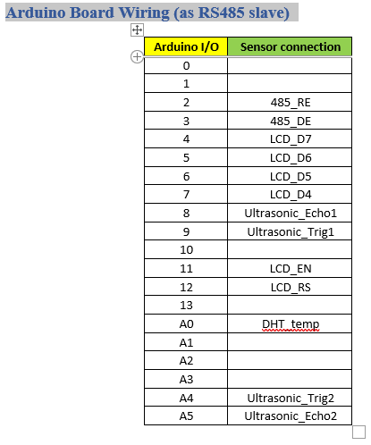
In this project, we are going toimplement RS-485 protocol in communication between two Arduinos using MAX485module. This module uses 5V as operating
voltage and has pinoutconfiguration as shown in the following table.
RS-485 module as transmitter
In order to be used as a transmitter, RE pin and DE pin must beconnected to 5V, and DI pin is connected to TX. Data is sent from Arduino TXpin to module DI pin, then data will be sent through AB.
RS-485 module as receiver
In order to be used as a receiver, RE pin and DE pin must beconnected to GND, and RO pin is connected to RX. Data received by AB will besent to RO pin that is connected to Arduino RX pin so the data can be read byArduino.
RS-485 can be implemented into three types of serialcommunication system: simplex, half-duplex, and full-duplex. But in thisproject, we are only implementing simplex and half-duplex.
2.PLC
1)Features
The features of XGB system are asfollows.
(1) The system secures the followinghigh performances.
(a) High Processing Speed
(b) Max. 384I/O control supporting small & mid-sized system implementation
(c) Enough program capacity
(d) Expanded applications with the support of floating point
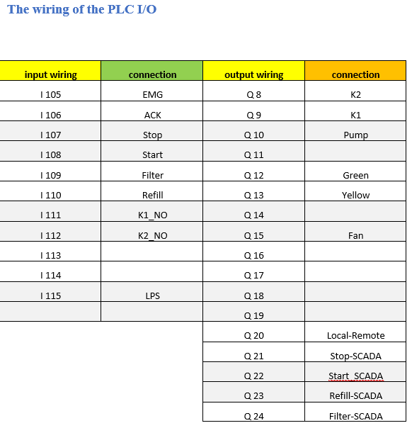
2)Input &Output wiring terms
Sink Logic
For a sink logic, an NPNtransistor provides a path to ground for the electrical load. For anNPN transistor circuit to work, it must be connected to a PNP transistorcircuit. In other words, a sink logic circuit needs to be connected to asource logic circuit.
Figure 1 shows a sinking digitaloutput that is connected to a sourcing digital input. The input circuitis connected between the positive power supply side (Vcc) and NPN transistor.
Source Logic
For a source logic, a PNPtransistor provides a path to voltage for the electrical load. For aPNP transistor circuit to work, it must be connected to a NPN transistorcircuit. In other words, a source logic circuit needs to be connected toa sink logic circuit.
Figure 2 shows a sourcing digital outputthat is connected to a sinking digital input. The input circuit isconnected between the PNP transistor and power supply GND (0v).
3)XBG systemconfiguration
XGB series System Configuration is as follows. Expanded I/O moduleand special module are available to
connect maximum 7 stages for “S” type and 10 stages for “H” type.Expanded communication module is available
to connect maximum 2 stages
4)Downloadcable
PLC communication may require various cables and connections fromRS232 serial, to Micro USB, to Cat5e Ethernet. A range of specialized PLCcommunication cables is available for PLC programming and I/O expansion. SinceCPUs provide many different communications port possibilities, it is helpful toknow exactly which communications cable is required. LS PLC XGB Series PMC-310SLoader Cable Connection cable (PC to PLC), 9pin-6pin.
Alternative Option was used USB as a download cable due tounavailability of this special cable
5)Names of Part and Functions
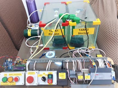
First of allthis project designed to be part of water treatment plant, as we can see in thefigure below that we have two main tanks in this project the tank on the leftis called Tank1 and the one on the right called Tank2 all the process will doby using tank1 like the federation and level controlling. Regarding to thestorage tank on the right we can storage the water after doing the process inthe Tank2 for the further use.
We have usedtwo ultrasonic sensors to calculate the level of each tank because the PLCdon’t have any analog input, we added these sensors to add more options to ourproject and its part of stability and acuity.
The final installation shown in thefigure below
thesensor number 1 called Level1 or L1 on the on-built drawing and its posiotined on the tank 1tomeasure its level and the L2 is a level transmitter of the tank 2. accordingto the logic inside the PLC the L1 make sure that Tank1 is full of water beforestarting the fiteration process and L2 is make sure that we have water whateverthe amount was before starting the pump. Also both of these sensors take partin the truning off the pumps. When level of water become shallow some timer inside the PLC start caounting toturn of the specific pump.
Water circulation processWater circulationprocess is oneof the crucial parts of this project we’ve used two pumps to fill or suck thewater from the tanks and their positions showing in the figure below
The attached filter and its pump to the Tank1 is themain processing unit available in this project and they have a Low-PressureSwitch or LPS and it prevent the pump to work without water during theprocessing phase.
Anyindustrial plant should have a local control panel that can control someprocessing options form the field so in this scenario we added such a coolcontrol panel to give an option for controlling the process locally without theSCADA system, we can choose either remote or local process by selecting from aremote switch on the SCADA main screen.
Howit works
Theplc continuously checks all sensors and will be ready to perform if there areno emergency or error. The benefit of emergency pushbutton is use for shoutingdown the entire plant and being in the alarm more till the emergency get to itsnormal position. The acknowledge pushbutton can be used reset all the programsinside the PLC like timers and other codes. The RUN indicator shows that theprocess in so doing, but the alarm indicator show both errors and emergency bydifferent blinking speed. by using the selector we can choose either filtrationprocess or refill after selecting the proper process we can press start to performthe logic and stop to cancel the logic even in the middle of the process.
ThePLC will work like this according to the logic inside- · Check the water level in the Tank1
- · Check the selector position
- · Check the remote/local status of the SCADA
- · If the local control was selected and there is noalarm the pump will start
- · After 1.5 minute the PLC will check the LPS for thepressure
- · After 2.5 minute the PLC will turn off the pump andrun the pump1
- · When the level in Tank1 reach the shallow level pump1will turn off
- · If the selector was in the Refill position and theoperator pressed start
- · The PLC will drain the storage tank to the Tank1
- · If the PLC temperature exceed the limit of 35C thecooling fan will start
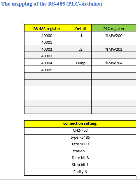
This fan has been designedto prevent the PLC from overheating and its controlled by a TT temperaturetransmitter connected to the Arduino and all the data transferred by Modbusprotocol to the PLC to take control of the fan if the temperature rose above 35C it will run the cooling fan and if the temperature was or will be under 35 Cit will turn it off.
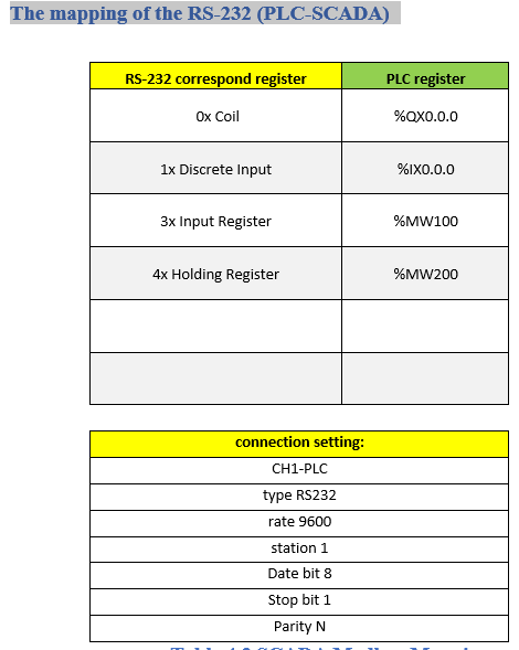
use only 3 pins to connect PLC with PC (SCADA)


_ztBMuBhMHo.jpg?auto=compress%2Cformat&w=48&h=48&fit=fill&bg=ffffff)



Comments
Please log in or sign up to comment.