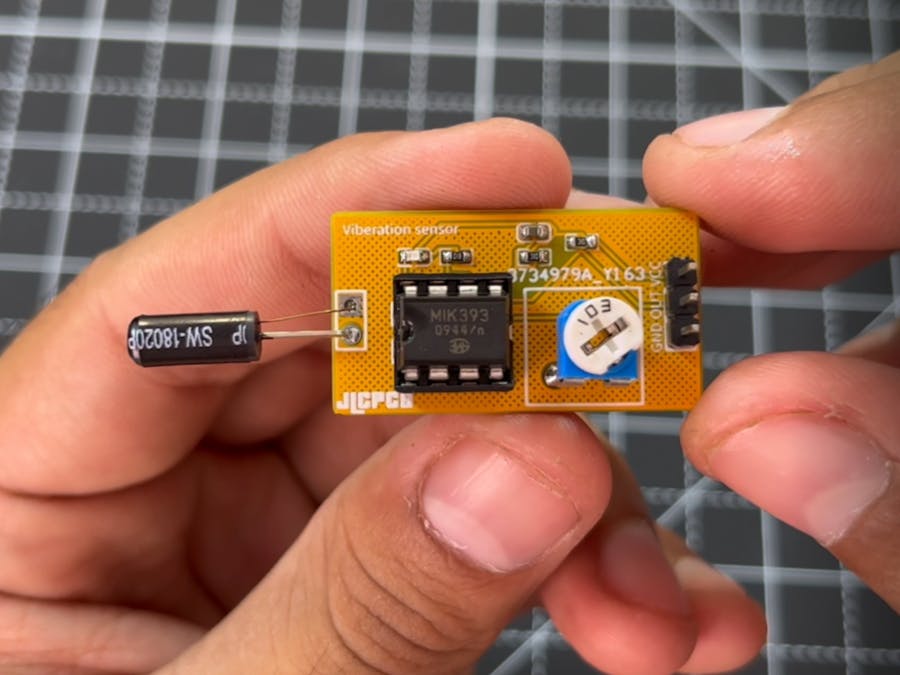
Recently, I got a vibration sensor from one of my friend, which is highly sensitive to vibrations and I want to convert this into a fully fledge vibration sensor module. The sensor is SW-18010P has two wire interface. This one is also known for waterproof action, shock spring switch. We will use this sensor with operational amplifier to get a digital output. This project is brought to you by JLCPCB- China’s leading PCB manufacturer. Offers the best prototyping service in $2 for 5 pcs of 2layer boards. Visit JLCPCB to know more about the services and capabilities. Get your Quote now and get huge off on first SMT assembly order.
SW-18010P sensor:This sensor has a spring inside, not any type of directional/ angle vibrations. Sensor can be triggered using a simple hit on the outer cover of the sensor. The switch is open circuit (off state) when it is static and has a 10Mega ohm open circuit resistance. Internal connections (metal surface) touch with each other to turn on the sensor.
The switch become close and possess a small 5-ohm resistance which allows 20mA of max current. SW- sensors comes in a lot of packages which can be seen all over the internet. Some of them have high sensitivity or some are made for high power ratings.
Operational amplifier as a comparator:We are using concept of the comparator, so it is must to know about this configuration of operational amplifier. basically, it is the open loop configuration of the op-amp which is used to provide the logical output according to the input. The input signal is get compared, we can set the reference using a 10k potentiometer which then used to set the sensitivity.
Here in this project, we are using non inverting comparator, the signal is given to non-inverting terminal and inverting terminal is free to set the reference accordingly. See more details about different configuration from here.
Components required:- Lm393 Operational amplifier
- SW-18010P Vibration sensor
- 5v battery
- Small SMD led
- 10k, 1k resistor
- 100nf capacitor
- 10k potentiometer
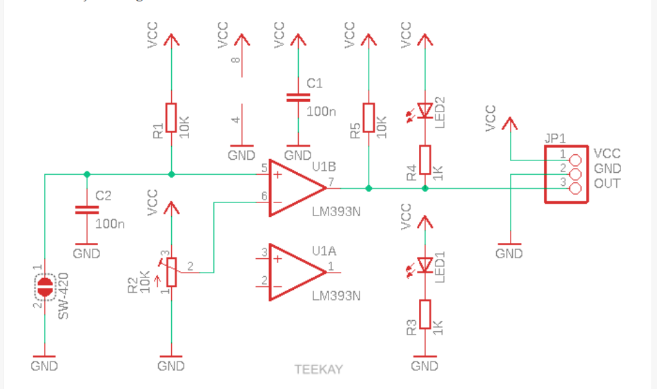
LM393 consist two operational amplifiers in an 8-pin package. We are only using one of them to maintain the sensitivity settings. 10k resistor is used to set the reference voltage on the non-inverting input of the OP amp.
100nf capacitor to reduce the overall power lines noise from the circuit. We are using operational amplifier as a comparator. When vibration is detected, the sensor will make the non-inverting pin to low and we got inverted output. A led is connected to output which glows accordingly. The output is active high normally and goes to low with the sensor. Sensitivity can be adjusted using 10k potentiometer which works with the circuit in comparator mode. See the full comparator details from here.
Pcb files:I designed the PCB files according to the revised circuit diagram, I used SMD components to reduce the size of the PCB but on the other hand I am using DIP socket based integrated circuit because it is easily available in the market. If you want to go with the same designs then download from here, or made one using the circuit diagram given above.
For my circuits and PCB, I always use JLCPCB because it is the most affordable pcb prototyping service up to 6 layers. And also deals in SMT assembly, stencil, PCBA and 3D printing. Get Quote now and try the best pcb prototyping just in $2 for 5pcs of 2layer board. Register using this link to get PCB coupons of worth $54.
Setting the reference:LED always turn on/off until proper biasing is done at the inverting terminal through potentiometer. Just rotate it very precisely till the LED get off. This is the settings to the maximum sensitivity and you will get a digital high signal on output. You can also lower down the sensitivity by rotating more and more.
Project demo:Whenever a vibration is detected, the LED will turn on making the output at logic low. For applications like motor driving an external PNP transistor can be used as a switch. Now if you ask what is difference between using the sensor normally or using it with operational amplifier. First the sensitivity is variable, secondly now you are getting digital signal and third it will lower down the unwanted noise in the circuit produced by internal spring of the vibration sensor. Once again, a very thanks to JLCPCB for the PCB board samples.


Comments
Please log in or sign up to comment.