


Hardware components | ||||||
 |
| × | 1 | |||
| × | 10 | ||||
 |
| × | 1 | |||
 |
| × | 3 | |||
 |
| × | 3 | |||
Hand tools and fabrication machines | ||||||
 |
| |||||
 |
| |||||
 |
| |||||
 |
| |||||
Building a 10 button transportcontroller for Studio One with an Arduino
This project is to build a 10 button transport controller with buttons for:
- play, stop, record
- insert marker, previous marker, next marker
- previous bar, next bar
- previous arranger section, next arranger section
The play and record buttons light up when active, and there is backlighting for the top switches.
Basic assumptionsYou have installed the Arduino software and gone through the first few basic lessons, including understanding how to import a new library and install it.
You are familiar with Studio One, including the options dropdown.
This software may work with other daws, but I have only tested with studio one. You may have to deal with a different set up approach within other daws.
Parts required:
- Arduino Leonardo (other Arduino boards could be used, but this one natively supports midi over USB libraries and has the required number of pins without having to use io expansion chips)
- Setof 10 buttons ( I used arcade style buttons that could be lit with leds. Other buttons will definitely work)
- Acase to house the project (I built one out of some scrap 1x4 I had kicking around, but use what you want, with the caveat that it has enough depth to hold everything).
- Connectingwire and terminals (I used hookup wire with crimp connections for the switches and pins for the Arduino, but soldering the connections would be better and require less work. I wanted the ability to remove them easily while figuring the wiring out, thus connectors)
- Ledsand resistors (optional for backlighting if desired)
Tools required:
(For building the connecting wires)
- Soldering iron, solder
- Wire cutters
- Wire strippers
- Multi meter
- Crimping tool
Note- I’m not going into building the case. I’m a hack woodworker and built mine quickly and poorly. Use what you like.
Assembly
(To keep things simple, I used strictly the digital pins, wired directly. There are more elegant solutions, but this worked for me. )
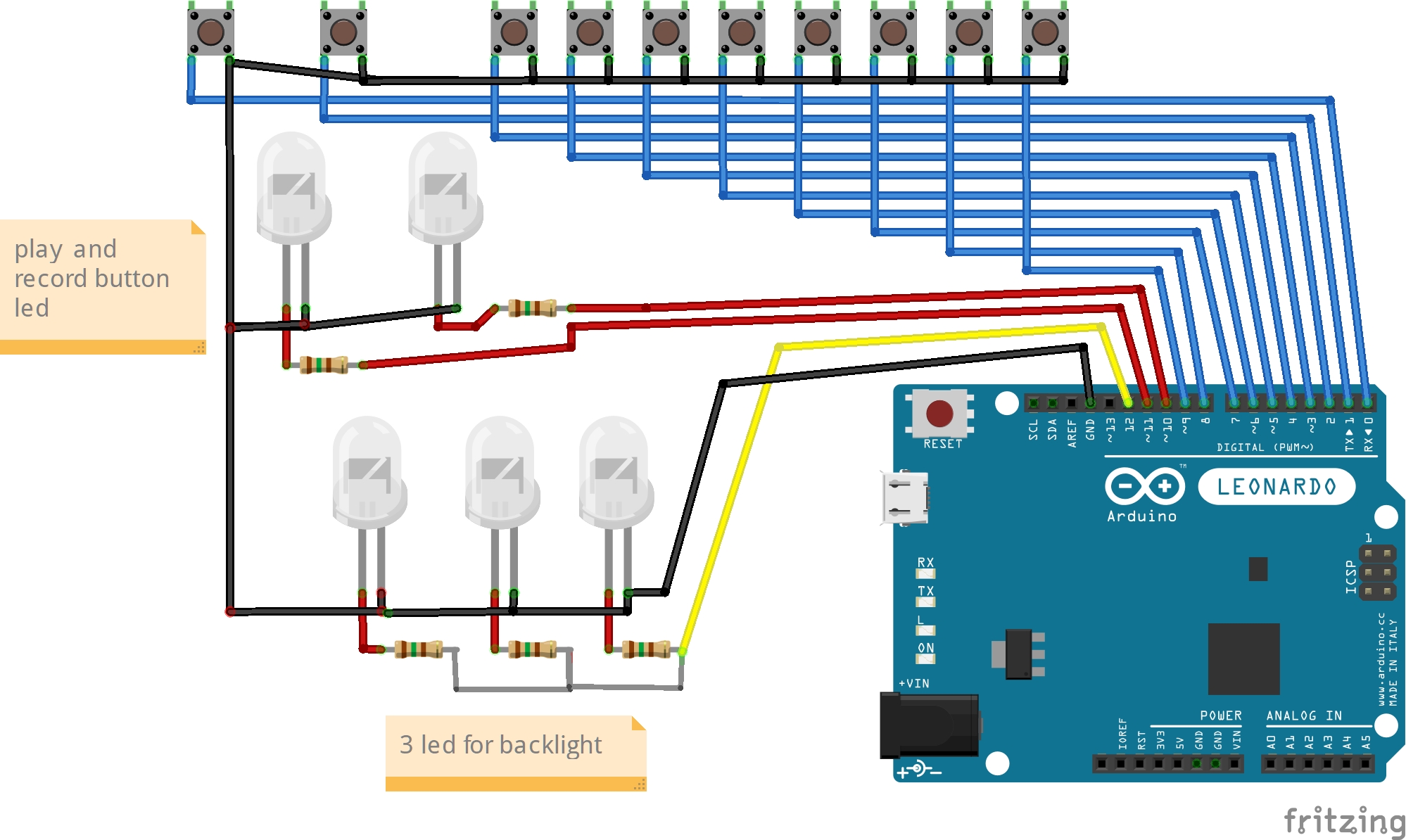
I used:- digital pins 0-9 for my buttons,
- pin10 for my record button led,
- pin11 for my play button led,
- Pin12 for my backlighting
- Power/midi is through the USB cable
- layout your switches and components, including the Arduino. Figure out where you want everything positioned, drill the holes in your case, dry fit buttons. By doing this it should prevent basic errors such as wiring that’s too short etc. Make sure to allow space for connectors if you are using them.
- create a grounding scheme. All switches and leds go to a common ground. Either use aground terminal strip, or do what I did and jump the ground wire from one connection to the next. Connect each switch with a ground on one of the two connectors. Connect leds on the appropriate connectors (leds only work one way)
- Wire the other switch connectors back to digital pins 0-9
- Wire the record led to pin 10 (make sure the appropriate resistor is in place)
- Wire the play led to pin 11 (make sure the appropriate resistor is in place). Note: most buttons with leds include a resistor in the button itself
- wire any back lighting leds to pin 12 (make sure the appropriate resistors are in place). I used 3 blue leds, wired in parallel, with a 120 ohm resistor on each, positioned between my top 3 sets of buttons. This back lighting is entirely optional, so skip it if you wish.
I started building my code based off of this project:
https://www.musiconerd.com/build-this-midi-controller-using-an-arduino-the-transport/
Then switched to using a different library than specified in the above project.
https://github.com/tttapa/Control-Surface
(This is a library specifically designed for building midi controllers. It is very powerful. Peruse the examples for ideas)
This library gave me easier access to receiving midi messages to light the led buttons.
I stripped out parts of the code that I didn’t need and modified it for ten buttons.
After switching to the new library I’m pretty sure I could trim it down further, as functions such as debounce are built into the new library, but it was working, so I didn’t mess with it.
Using sample code from the new library, I added the ability to receive midi and light buttons.
I also added a basic command to leave pin 12 high, giving it power for the backlight leds.
The Sketch can be copied here:https://github.com/Coldsalt/studiotoys
Settings in Studio OneTo make everything work in Studio one, I set up 2 controllers:
1) a generic controller that is set to receive button pushes from the Arduino. I set this: receive to arduino and send to none.
Then use midi learn in studio one to set the actions of the buttons. If you are un familiar with using the midi learn function, here is a tutorial:
https://www.youtube.com/watch?v=Vq0GMDvagi4
2) The Mackie Control preset ( choose mackie control from the drop down menu) to receive play and record messages back to light the button leds. Set this: receive to none and send to arduino.
Using studio one’s built in midi monitor ( double click the midi icon in the bottom left corner), I figured out the midi note messages for play and record that were being sent to the Arduino from the mackie controller preset.
To figure these out, the easiest way I found was:
- go into studio one-preferences - external devices and default everything but the mackie hui to none.
- go back to the midi monitor, and filter for send messages.
- pushbuttons in studio one (specifically play and record) and see what comes up in the midi monitor.
There are other messages that stream out, but it becomes fairly clear what messages are tied to individual buttons.
For example:
- play is midi note Bb(6), channel 1
- Stop is midi note A(6), channel 1
- Record is midi note B(6), channel 1
Be aware, studio one uses a nonstandard midi numbering. So thedeclared note in the midi monitor is actually an octave out (the midi monitorwill show A(5) when the actual value is A(6)) when compared to standard midi.When entering the value in the Arduino sketch, adjust the value one octave upfrom what the monitor shows. The hex value in the monitor is correct, if youuse that.
My Arduino script is set up for play and record lights. Just copy and paste the specific line of code and change the midi note for other lights.
Final thoughts:
My next step with this project will be to run a second line off the record light pin to trigger recording warning lights mounted outside my studio.
Please ask if you have any questions or improvements.
Steve


Comments
Please log in or sign up to comment.