


Hardware components | ||||||
 |
| × | 1 | |||
| × | 1 | ||||
| × | 1 | ||||
| × | 6 | ||||
| × | 2 | ||||
| × | 8 | ||||
| × | 12 | ||||
| × | 1 | ||||
| × | 1 | ||||
| × | 1 | ||||
| × | 2 | ||||
| × | 1 | ||||
Software apps and online services | ||||||
 |
| |||||
Hand tools and fabrication machines | ||||||
 |
| |||||
I’ve always been fascinated by the Christmas displays that fill the streets at Christmas time. This year I decided to create my own version of these. My goal was to come up with something convincing using the most basic and cheapest electronic components as well as recyclable material, without using any third-party library in the code, which makes this a perfectly beginner friendly project.
Now who says Christmas tree decoration, says flashing colorful lights, but there’s Santa Claus too, who (as you can see in the video), hovers happily in the smiley night sky riding his sleigh.
System OverviewHere’s how the system transitions from one state to another in response to user inputs:
Implementing pseudo-parallelism
As you can see in the video, there are multiple things going on at the same time. Arduino has a single core processor and doesn’t support multi-threading. In other words, there’s no way of implementing true parallelism, but we can still give the illusion of parallelism with a sensible ordering of instructions. This section explains how to do that.
As you can see in the code, the stepper motor and the RGB LEDs use delay() to keep their values for specific periods of time. Delay() is an Arduino built-in function for dealing with timing tasks. It’s not the only choice, there are better alternatives such as millis(), but for the time being, let’s just stick with it.
Delay() is a blocking function, which means that when it is being executed, the processor is stalled and does not react to anything until the end of the delay. This makes it difficult to write concurrent code.
The workaround is to break down the longest delay into a sequence of shorter delays, and to check for external events (a button press in this case) before each one of these short delays.
For instance, in a purely sequential mindset, one would set the RGB LEDs to a color, wait for 1000ms, then perform a motor step (which lasts 8ms in my case), then set the RGB LEDs to another color, wait for 1000ms and so one. As you can imagine, the motor will not run smoothly.
Instead, a better way to do it is to set the RGB LED color and then perform as many motor steps as necessary for the 1000 ms to elapse.
To see it more clearly in code, here’s a snippet of the code block that implements this idea:
/*...*/
//perform RGB light animations while rotating the motor
  //(or not, depending on the events on the motor button):

  uint16_t RGBlight_pulseDuration[4] = {1000, 500, 300, 100};

  for(uint8_t d=0; d<4; d++){
    //calculate the number of motor steps we need to do sequentially
    //so as to keep the rgb color ON for RGBlight_pulseDuration[d] milliseconds
    //(a motor step lasts 8 milliseconds)
    uint16_t nb_motor_steps = uint16_t(RGBlight_pulseDuration[d]/8);

    //for each color c
    for(uint8_t c=0; c<nb_colors; c++){

      //set the first set of rgb leds to color c
      set_rgb_light( R[0], G[0], B[0], colors[c], 255);

      //set the second set of rgb leds to a color thats complementary to color c
      set_rgb_light( R[1], G[1], B[1], colors[nb_colors - c - 1], 255);

      //rotate the motor while listening for button pushes
      for(uint16_t i=0; i<nb_motor_steps; i++){

        flag motor_status = one_motor_step(1);

        //motor_status is a flag that indicates what to do in case a button
        //was pushed during motor rotation
        if(motor_status == GOTOLOOP)
          return;
        }
    }
/*...*/a. The wiring
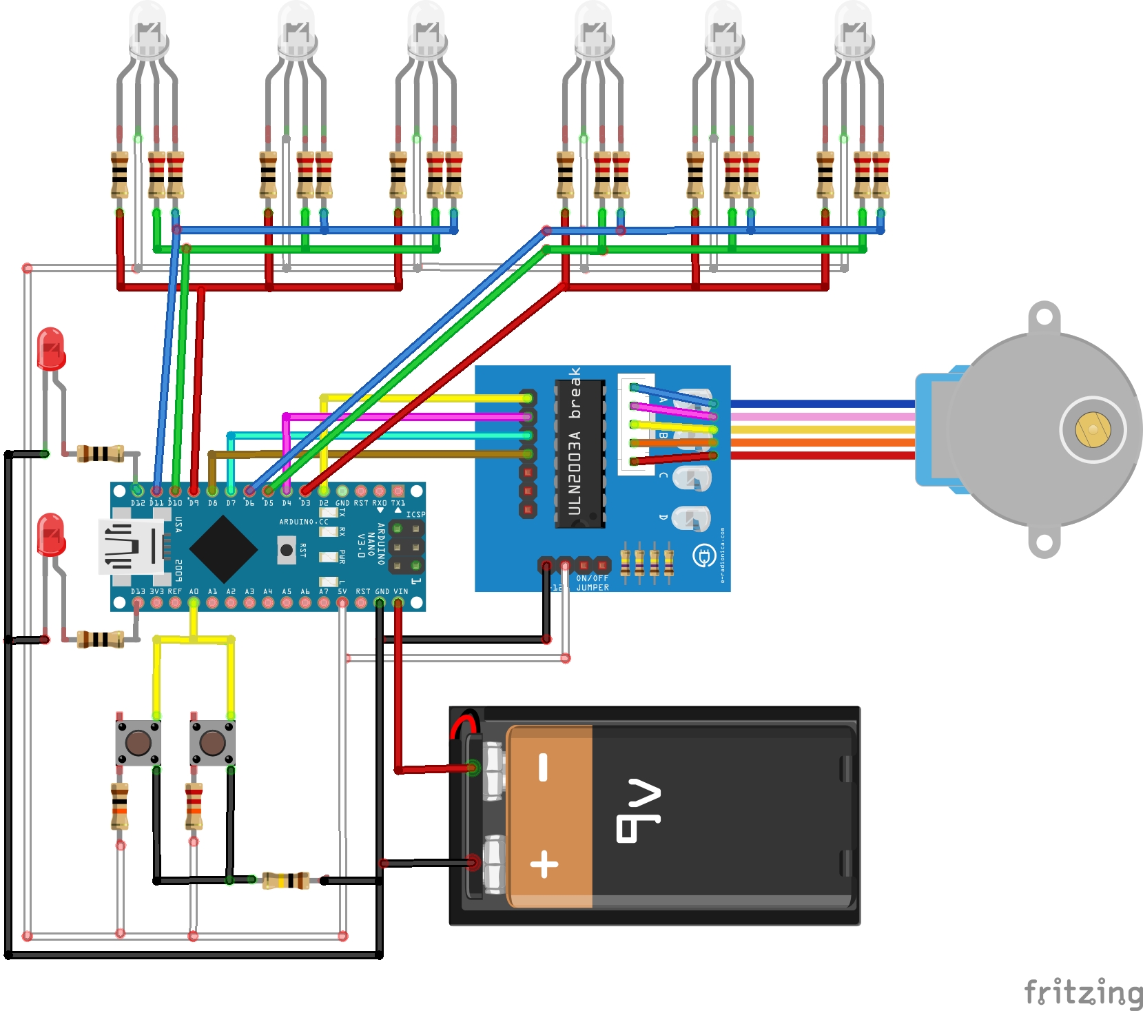
There are multiple ways to connect a push button to an Arduino. I chose to wire them all to the same analog input pin to save up the digital I/O pins for the rest of the components. In such a setup, the trick is to use a different resistor value for each button, this way a press on button 1 leads to a range of voltages on the analog input that are different from those created by a press on button 2, and that’s how multiple buttons are identified.
b. The control flow
How can we use a button to switch between the different states of a component?
Let’s take the example of the stepper motor, the same principle applies to switching between the different modes of the RGB light animations.
In order to change the state of the motor from ON to OFF and vice versa using a push button, we need to keep track of the state of the motor. This can be achieved using a global variable, whose initial value is associated to the initial state of the motor (in our case, that’s ON). This variable gets incremented each time the user pushes the button, such that its even values trigger the ON state and its odd values trigger the OFF state of the motor.
Here’s the code snippet that implements that:
flag listen(){
  /*
  Catch button presses
  Each button returns a specific range of values in analog input A1
  */
  int buttonState = analogRead(A1);
  if(buttonState > 800 && buttonState < 850 ){

    //this range is particular to the lights button
    //wait until the user finishes the press
    while(buttonState > 800 && buttonState < 850 ){
      buttonState = analogRead(A1);
      }

    //increment the global variable that stores the number
    //of pushes on the lights button
    nbpushes_lightsbutton++;

    //return from all functions until you reach the loop()
    //where we decide which light effects mode to trigger
    //depending on the value of nbpushes_lightsbutton
    return GOTOLOOP;
  }
  else{
    if( buttonState > 900 ){
      while(buttonState > 900 ){
        buttonState = analogRead(A1);
        }
      nbpushes_motorbutton++;
      return STAY;
    }
  }
}
c. A word about switching between different modes of RGB light animations
I strongly invite you to read the code before going through this section, as it dives into algorithmic details of the code.
In my opinion, the best way to switch from one lights mode to another is to return from all functions until reaching the loop, an there decide on which lights mode to trigger based on the number of pushes of the lights button. Why is that?
In this system the RGB lights are either on mode 1 or on mode 2. We’ll name the functions that implement them lights_mode1() and lights_mode2() respectively.
Imagine that the way we switch between the 2 modes is by calling lights_mode2() from inside lights_mode1(), and vice versa.
So here goes the scenario. Lights are on mode 1 ( which means that the program counter is pointing to an instruction in lights_mode1() ), a lights button push occurs, and we call lights_mode2(). The lights are now on mode 2 and suddenly another lights button push occurs and we call lights_mode1(). While on mode 1, another lights button push happens… and so on and so forth. We’re clearly heading towards a stack overflow, since we are in a situation of infinite nested function calls. That’s why the safest way, is to get out of everything once we catch a lights push button, go back to the loop(), which is the main() function in the case of Arduino, and decide on which lights mode to run.
The solderingTo make a compact size control box I soldered everything on a 5cmx8cm perfboard. On one side there’s the arduino nano and most of the resistors, on the other side there’s the components that the user interacts with (namely the push buttons and the 3mm LEDs). The RGB LEDs and the stepper motor are extended using wires 1.3m long on average.
As for the sleigh and the snowflakes, you can find such ornaments for sale online, you can also design yours and 3D-print them, or laser-cut them on wood or plexiglass. I made mine by hand using Amazon delivery packages that I’ve been piling up for a while, I colored them with electrical isolation tape, and used thin rope to decorate the borders of the snowflakes, the sleigh and for the reindeer harnesses. To make the cardboard thicker I stacked up two or three layers with regular glue. The wire holding the moon and the stars is a plain electrical wire.
- Using delay() forced me to interleave the instructions in a way that made it difficult to separate the services of each component (the motor, the buttons, the RGB lights). Using millis(), or a library that offers timing functionalities will make it easier to structure the code into classes. That way, the software will be more understandable and scalable.


Comments
Please log in or sign up to comment.