


Hardware components | ||||||
| × | 1 | ||||
 |
| × | 1 | |||
| × | 1 | ||||
 |
| × | 1 | |||
| × | 1 | ||||
 |
| × | 1 | |||
| × | 1 | ||||
| × | 1 | ||||
| × | 1 | ||||
| × | 1 | ||||
| × | 2 | ||||
| × | 1 | ||||
 |
| × | 2 | |||
| × | 1 | ||||
| × | 1 | ||||
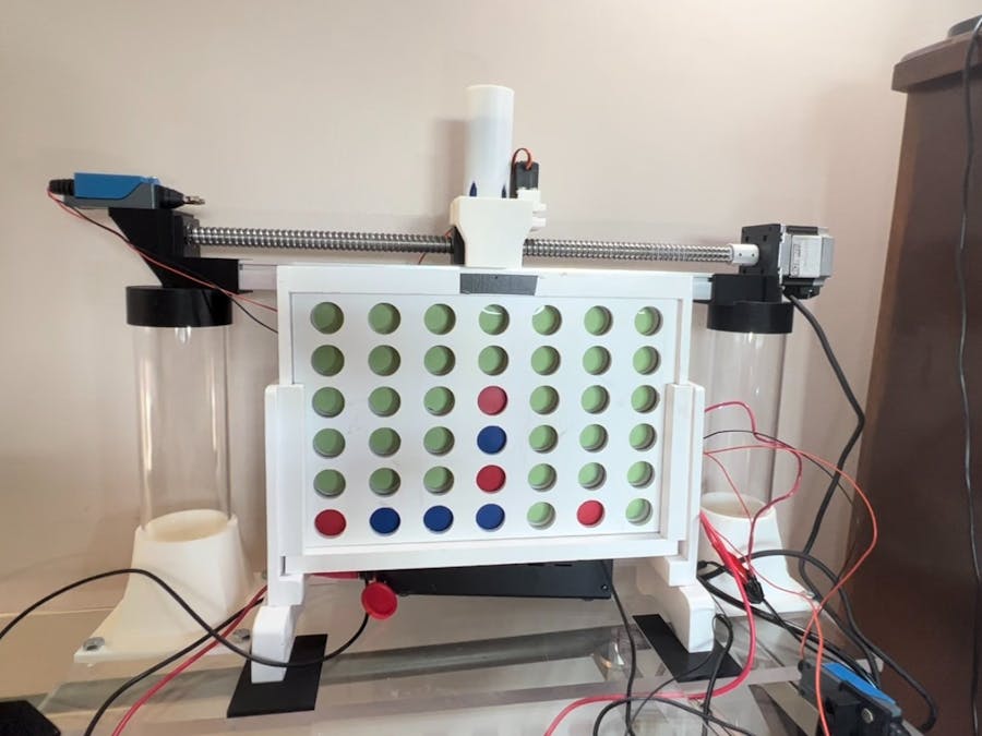
This project is a robot v.s. human Connect 4 game where the human plays the robot on a physical game board as if they were playing another player. The vision is to have a camera scanning the board and then motors move a dispenser along the top of the connect four board to drop in a piece for the robot. The human player would place their piece in a column, then the computer scans the board and uses an algorithm to determine the best column to place a piece. Then, the robot navigates to the correct column and drops a piece.
MotivationThis project is a way for me to learn about robotics, OpenCV, motors, circuits, and coding. I thought it would be fun to make a robot I could play a game against and Connect 4 seemed like a simple game for my first robotics project.
Current Version of ProjectMy project is currently a fully functional prototype. The robot needs to be plugged into a computer to run. (This project uses a PocketBeagle, which is nearly equivalent to a Raspberry Pi.)
Video of Project:
Building the ProjectStep 1: Text Based Game
I based my project off of Keith Galli's virtual Connect 4 game: https://github.com/KeithGalli/Connect4-Python
I removed all the visual pygame elements and instead made it text based.
Step 2: Testing Components
The first component I tested was the 16x2 character LCD display. Wiring was very simple but I had to install the adafruit_character_lcd.character_lcd library to connect to the display. A potentiometer controls the contrast of the display.
Next I worked on connecting the stepper motor. The stepper motor will move the piece dropper along the top of the Connect 4 board to the right column via a belt and pulley or a linear actuator (the current prototype uses a stepper motor to control a linear sliding rail). I used a stepper motor driver in order to more easily control the stepper motor. The stepper motor driver requires a 5V input in order to control it but the PocketBeagle can only output 3.3V. I used a Logic Level Converter to convert the signals from 3.3V to 5V. I used an external power supply (5V, 2A) to power the stepper motor. Wiring was simple and I found some test code to use from https://github.com/petebachant/BBpystepper.
Next I connected the 360 degree continuous rotation servo motor. The servo motor will be used in the piece dropper to drop one piece into the right column (in hindsight choosing a continuous rotation servo was a mistake since it has poor positional accuracy and control). The servo motor also required a 5V power supply and I controlled the servo through the PocketBeagle's PWM pin. I used servo motor test code from my instructor, Eric Welsh.
The last piece of hardware to connect was the USB camera. Connecting the camera required connecting (I just soldered them) the VB and VI as well as the ID and GND pins together. To test the camera, I used some basic code in the terminal:
python3
>>> import cv2
>>> cap = cv2.VideoCapture(0)
>>> ret, frame = cap.read()
>>> cv2.imwrite("temp.jpg", frame)
I created a custom PCB for this stage of the project: https://github.com/SMSARVER/ENGI301/tree/main/Project_2
Step 3: OpenCV Code
Writing the OpenCV code was the most challenging part of this project. I started writing code to work on an image of a Connect 4 board and then modified it to work with photos from my USB camera. I put a green background behind the game board to make it easier to detect open spaces. The program takes a picture of the board and outputs a 6x7 array (what the main game code uses to represent the board) with the value of each space on the board. I used an OpenCV function called HoughCircles to detect all circles on the original image and looked at the color of the pixels in the center of each circle. This creates an array of circles and their colors which I then sort based on their y and x positions in the image to create the 6x7 array. Below is a photo of the code detecting the red circles on an image.
Step 4: Choosing a better motor
At this point in the project I determined that using a pre-constructed linear actuator instead of designing my own would be best to save time and focus on the parts of the project I was more interested in. The image below shows a NEMA 23 stepper motor attached to a linear sliding rail. This solution allowed for extremely high positional accuracy as well as decent speed (about 1 inch/second travel speed). In hindsight, this motor is overkill for my application.
I wrote a script using the Adafruit_BBIO.GPIO library to control the position of the piece dropper on the linear actuator. I had to test what ranges of speeds worked for this motor as well as write code to smoothly accelerate the motor (more details in the code overview video).
Step 5: Designing the Piece Dropper
I needed to come up with a way to store twenty-one Connect 4 pieces and release them reliably one at a time into a narrow slit at the top of the game board. A simple design I thought of was to have all the pieces stacked in a tube and then knock off the bottom piece with a bat. I used a continuous rotation servo motor to rotate the bat to push a piece through a funnel and onto the board. After testing this mechanism I realized that the continuous rotation servo motor did not have the positional accuracy I need. 90% of the time it rotates 180 degrees to drop one piece but occasionally it rotates too much or too little, dropping two or no pieces. I plan to use a stepper motor for this application in the future.
Step 6: Designing the Structure
I wanted a structure that held the linear actuator above the game board, provided a space for the electronics, and positioned the camera and lights at the optimal location. I chose to make my project out of plastic since it is easy to work with (although choosing acrylic was a mistake since it is brittle). I bought a plastic base and mounted two thick plastic tubes towards the edges to hold up the linear actuator. I 3D printed the mounts and then tapped the plastic and used bolts to secure it. A second sheet of plastic and a second tube positions the camera and light in front of the game board.
I designed 3D printed mounts for the linear actuator, limit switches, and the camera and light. I had to take very careful measurements in order for everything to fit together in the right positions.
Step 7: Limit Switches
Limit switches are important for safety and for positional accuracy. My robot uses two limit switches on either side of the linear actuator to detect when the piece dropper goes off the rails (pun intended). I also use the limit switches to start each game in the correct position (the robot starts the game by hitting a limit switch and by knowing the distance of the switch to a column on the game board it can accurately move there).
Wiring:Currently my wiring is a bird's nest on a breadboard but I may make a PCB or create a wire management system. I designed a PCB for a previous version of this project before I changed motors: https://github.com/SMSARVER/ENGI301/tree/main/Project_2
This image showing the PocketBeagle pins will be helpful in wiring:
LCD Display:
LCD_VSS to P2_15 (ground)
LCD_VDD to P2_13 (v_out)
LCD_V0 to Potentiometer center pin
LCD_RS to P2_10
LCD_RW to P2_15
LCD_E to P2_17
LCD_D4 to P2_2
LCD_D5 to P2_4
LCD_D6 to P2_6
LCD_D7 to P2_8
LCD_A to P2_ 13
LCD_K to P2_15
Potentiometer right pin to P2_13
Potentiometer left pin to P2_15 (ok to swap P2_13 and P2_15 on potentiometer)
USB Camera
P1_5 to P1_7
P1_13 to P1_15
P1_7 to USB_VCC
P1_9 to USB_D-
P1_11 to USB_D+
P1_13 to USB_ID
USB_ID to USB_GND
Stepper Motor Driver (SMD), Continuous Rotation Servo (CRS), Power Supply 5V (PS5), Power Supply 30V (PS30):
CRS_- to P2_15
CRS_+ to P2_13
CRS_PWM to P1_36
PS5_- to P2_15
PS5_+ to P2_13
PS30_+ to SMD_VCC
PS30_- to SMD_GND
SMD_DIR- to P2_15
SMD_PUL- to P2_15
SMD_DIR+ to P2_24
SMD_PUL+ to P2_22
Stepper Motor:
Test the four wires for the stepper motor for pairs of continuity. One pair connects to A+/A- and and the other pair connects to B+/B-. For my motor blue was A+, yellow was A-, green was B+, red was B-.
Limit Switches:
I use two limit switches, LIM1 (left) and LIM2 (right) with cables A and B. There is continuity in the switch when it is not being pressed. I chose to wire the switch this way so that if a cable becomes disconnected then immediately I can notice a problem.
LIM1_A to P2_15
LIM2_A to P2_15
LIM1_B to P1_2
LIM2_B to P1_4
1K Ohm Resistor connecting LIM1_B to P2_13
1K Ohm Resistor connecting LIM2_B to P2_13 (must use a separate resistor)
See additional photos of wiring to aid you:
Libraries to install:
sudo apt-get install python3-numpy
sudo apt-get install python3-opencv
pip3 install adafruit-circuitpython-charlcd
sudo pip3 install Adafruit_BBIO
Code Overview Video:
GitHub: https://github.com/SMSARVER/ENGI301/tree/main/connect4
CAD Files for 3D Printed Parts:Please email me at sms27 at rice dot edu for the CAD files.
Limit switch and linear actuator support:
Dropper, bat, and funnel:
Camera and light support:
I plan to improve the fully-functioning robot by organizing wires, making small improvements, and solving mechanical and software issues. I also want to use "cron" to make my project automatically boot upon startup of the PocketBeagle. This way, my robot can be fully standalone.
Planned Improvements List:
- Make a wiring schematic
- Use stepper motor for piece dropping mechanism (For positional accuracy)
- Use a magnetic limit switch instead of a plunger limit switch (For greater accuracy. Plunger limit switch slightly bends plastic on contact so magnetic limit switch would eliminate contact altogether.)
- Add button and reposition screen to create a user interface
- Create wire management system and an updated custom PCB
- Improve the bot's algorithm to make it nearly unbeatable
- Making robot fully standalone and can run without being connected to a computer


Comments
Please log in or sign up to comment.