Hey hacksters!
Here I've posted a project I consider it would be too important if we can implement it to help patients who suffer of Asthma, Rinithis or any other illness caused by mites.
Let's give it a look!
The problemAsthma, rinithis and atopic dermatitis are allergies considered hereditary. The presence of mites in our habitat increase the symptons and the main reason isn't them but what they defecate.
Perhaps with the analog coprocessor kit I can't exterminate them but I could make their habitat uncomfortable and decrease the number of mites.
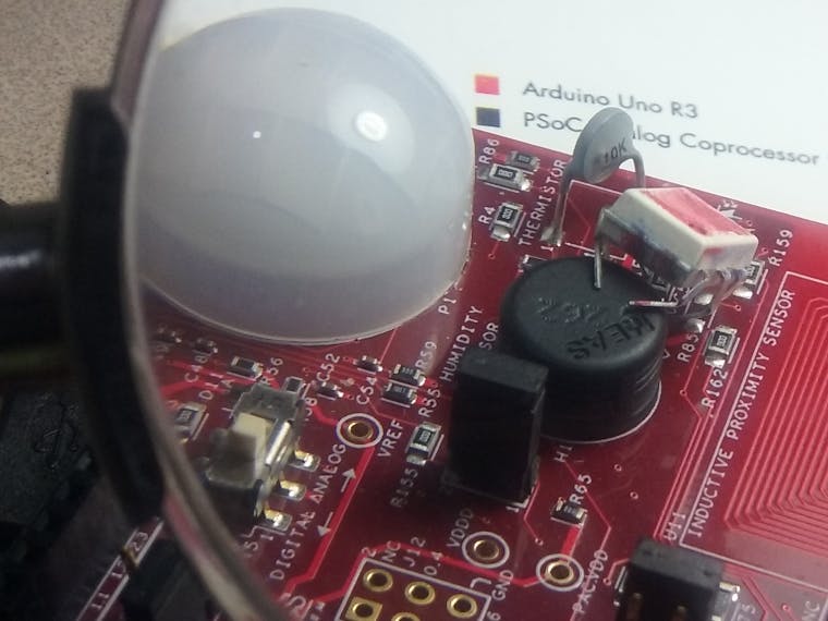
So, I "googled" about mites habitat and I found that mites need a relative humidity percent higher than 50% and a temperature condition between 20°C to 25°C. So I remembered that with the Analog coprocessor kit I could read temperature and relative humidity.
The proposed solutionI think that if we can monitor our bedroom environment for example, we can control the conditions and make all the possible for improve our lives with these illnesses. So, I wrote a code to use the analog coprocessor kit to read the humidity inside bedroom and the temperature inside and outside to know the environment conditions, then the measurements can be used to control the humidity with a kind of actuator I made, it could be an air dehumidifier, or just a ventilation system.
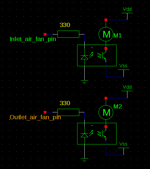
What I did: (Making the physical model (Prototype))- A bedroom representation with two fans, one of the fans takes out the air and the other enters it. I used a couple fans I found without use. They were drived throught two optoisolators (MOC3021).
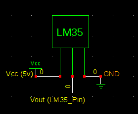
- I used a LM35 sensor to read the outside temperature and take a decision for example if we need to take any decision when the temperature is higher outside than inside and the humidity is higher than 50% too.
Code was done on Creator 4.0 IDE
-Blocks:
- CapSense. (Measure the Humidity sensor capacitance).
- Programmable voltage reference. (Voltage divider to measure thermistor).
- Thermistor. (Block used to calculate the temperature with the thermistor resistance).
- Operational amplifier. (To keep the reference voltage).
- Serial communication block. (UART communication).
- Scanning SAR ADC. (Read the Thermistor, voltage reference and LM35 sensors).
- Fans pins. (Digital outputs to drive the fans with opto-isolators.)
-Code
I saw the Cypress examples and I used the same variables and the structures to measure the humidity and temperature sensors.
The humidity sensor uses the CapSense, because the variation of the capacitance respect to a reference capacitance can be read as a humidity measurement using a equation given by Cypress.
The thermistor is read throught a voltage divider whose pins are:
- Pin_Vhi: High voltage ( P0[2] ).
- Pin_Vtherm: Thermistor voltage ( P3[5] )..
- Pin_Vlow: Low Voltage ( P3[7] ).
- Pin_Vref: ( 1[3]).
It is also important using the Thermistor block to calculate the thermistor resistance and then the measured temperature.
What I did first in the code was to put the constants that will be used, then define the global variables and Initialize the functions and the components (i.e. CapSense, ADC, UART, etc.)
In the main function after initialize the components and enable global interrupts, I called in the following order the other functions in the infinite loop, to do:
- Humidity reading.
- Temperature reading (both sensors).
- UART communication (send or receive data from/to an interface.)
- Take decisions.
In the last function which I called "Analisis" I put a kind of selection by the user, so, the users will can choose if they want an automatic mode or want to actuate the actuators (Fan system or Air dehumidifier) by themselves.
Programing the interface.Video.


Comments
Please log in or sign up to comment.