This guide was created on behalf of the Arm Software Developers team, follow us on Twitter: @ArmSoftwareDev and YouTube: Arm Software Developers for more resources!
IntroductionThis guide will walk through how to create your own USB microphone device using a Raspberry Pi Pico board and an external digital microphone. This project will leverage the Programming I/O (PIO), Direct Memory Access (DMA), and Universal Serial Bus (USB) capabilities of the boards RP2040 microcontroller (MCU).
USBUSB is an extremely popular standard, released in 1996, for wired computer peripherals, such as keyboards, mice, printers, scanners, and microphones.
The Raspberry Pi Pico board's RP2040 MCU has a "USB 1.1 Host/Device" feature, which allows you to either connect to an existing USB peripheral device (host mode) or create your own USB peripheral (device mode). The Raspberry Pi Pico SDK uses the TinyUSB library as its USB software stack.
The Tiny USB library is "An open source cross-platform USB stack for embedded system" that supports several types of MCU's including the Raspberry Pi RP2040. and has support for both device and host mode. We can use it's built in USB Audio Class support to transform our Pico into a USB microphone device.
Selecting a microphoneThe RP2040 MCU has a built-in 4 channel Analog-to-digital converter (ADC) feature with 12-bit precision, this could be used to collect audio from an external analog microphone, however we found the audio quality from the analog microphone to contain a lot of noise, so will be using a digital microphone instead.
There are two common interfaces for digital microphones:
- Pulse Density Modulation (PDM)
- Inter-IC Sound (I2S)
While the RP2040 does not have built-in support for both of these interface types, the super flexible Programmable I/O (PIO) feature can be used to create our own PDM or I2S peripheral interface in software. I will generate an output clock signal to the microphone on one pin and use another pin to receive data from the microphone. For this guide we'll be using the Adafruit PDM MEMS Microphone Breakout board.
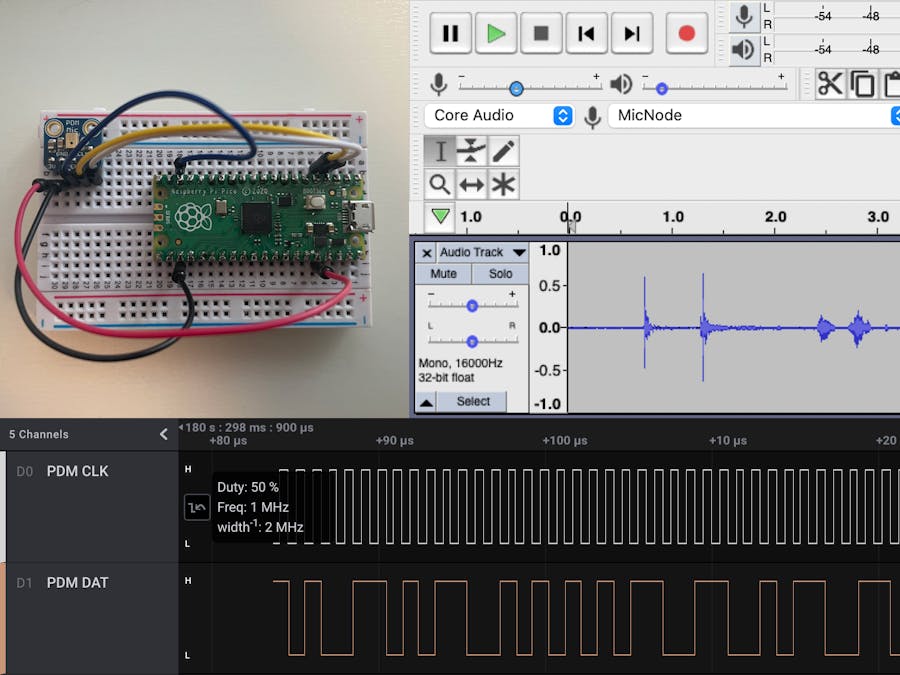
How does PDM work?When the PDM microphone receives the clock signal, it outputs a 0 or 1 signal based on the analog audio value it captures from the microphone. To capture audio at 16, 000 samples per second (16 kHz), the PDM microphone's clock input must be driven at 1.024 MHz = 64 x 16kHz and then the PDM's microphone data single can be filtered and downsampled. For each sample, the 0 or 1 output for 64 values are averaged to create a single 16-bit value between -32678 and 32767 for the sample.
You can use a logic analyzer, such as Saleae to view the PDM CLK and DAT signals.
The system will do the following:
1. Use the PIO to generate a 1.024 MHz clock signal into the PDM Microphone.
2. Capture a digital value from the PDM Microphone once per clock period using PIO.
3. The DMA will be configured to capture 1 millisecond of audio, with 16 kHz sample rate, 16 samples are generated every millisecond. The 16 samples will consist of 64 x 16 = 1024 bits.
4. Once the raw PDM data for 16 samples is received, it will use the OpenPDM2PCM library to filter and downsample the 1024 bit raw PDM data into 16 Pulse-code modulation (PCM) 16-bit audio samples.
5. Send the 16 PCM audio samples over USB to the PC.
Solder male headers on to your Raspberry Pi Pico board and the Adafruit PDM MEMS Microphone Breakout board so they can be plugged into a breadboard. See The MagPi's "How to solder GPIO pin headers to Raspberry Pi Pico" guide for more details on soldering pin headers to the Raspberry Pi Pico board.
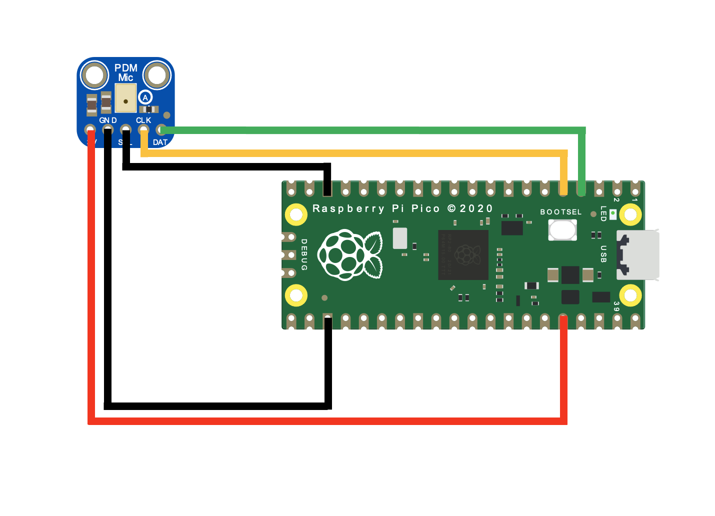
Once both items are soldered, place them on a breadboard and setup the wiring as follows:
+---------+-------------------+
| PDM Mic | Raspberry Pi Pico |
|---------+-------------------|
|    3V   |        3V3        |
|---------+-------------------|
|    GND  |        GND        |
|---------+-------------------|
|    SEL  |        GND        |
|---------+-------------------|
|    DAT  |       GPIO2       |
|---------+-------------------|
|    CLK  |       GPIO3       |
+---------+-------------------+
Note: Connecting PDM Mic. SEL to GND will result it clock out new data after the clock signal falls (goes from logic level 1 to 0).
You'll first need to setup you computer with Raspberry Pi's Pico SDK and required toolchains.
See the "Getting started with Raspberry Pi Pico" for more information.
Section 2.1 of the guide can be used for all Operating Systems, followed by the operating specific section:
- Linux: Section 2.2
- macOS: Section 9.1
- Windows: Section 9.2
Make sure the PICO_SDK environment variable is set.
export PICO_SDK_PATH=/path/to/pico-sdkIn a terminal window, clone the git repository and change directories:
cd ~/

git clone https://github.com/sandeepmistry/pico-microphone.git


cd pico-microphone
Create a build directory and change directories to it:
mkdir build

cd build
Run cmake and make to compile:
cmake .. -DPICO_BOARD=pico

make
Hold down the BOOTSEL button on the board, while plugging the board into your computer with a USB cable.
Copy the examples/usb_microphone/usb_microphone.uf2 file to the mounted Raspberry Pi Pico boot ROM disk:
cp -a examples/usb_microphone/usb_microphone.uf2 /Volumes/RPI-RP2/.You should see a new microphone device named "MicNode" attached to your system:
Now that we have the Raspberry Pi Pico board configured as a USB microphone, any desktop recording application, such as Audacity can be used to capture capture from the device over USB.
Download and install Audacity on your computer.
Once it is installed open the application, and select the "MicNode" device as the input.
Click the Record ⏺ button to start recording audio for the Raspberry Pi Pico. Press the Stop ⏹ button to stop recording audio.
We created our own USB microphone using a Raspberry Pi Pico board and external PDM microphone. The Raspberry Pi RP2040's PIO, DMA and USB hardware features were all used in this project along with the OpenPDM2PCM and TinyUSB software libraries on one of the RP2040's Arm Cortex-M0+ processors.
Our USB microphone captures PDM audio data from the PDM microphone, converts the PDM data to PCM format, and then sends the PCM data to the PC over USB all in real-time! Since the USB Audio standard is used for communications between the Raspberry Pi Pico board and the PC no custom software is needed on the PC side.
While this guide transfers the audio data from the Raspberry Pi Pico to the PC over USB, you can also use the pico-microphone library with an analog or PDM microphone, and perform on device Digital Signal Processing (DSP) to react to the board's audio environment without a PC.
Additional Raspberry Pi RP2040 resourcesFor more tutorials using the Raspberry Pi RP2040, check out these projects below:


Comments
Please log in or sign up to comment.