


Hardware components | ||||||
 |
| × | 2 | |||
| × | 2 | ||||
 |
| × | 1 | |||
| × | 1 | ||||
 |
| × | 2 | |||
Software apps and online services | ||||||
 |
| |||||
| ||||||
The device consists of a push-button remote control and a block of 8 relays for switching on and off the actuators. Communication via radio channel. Allows people with limited mobility to remotely control electrical devices (garden watering, lighting, etc.)
This is the simplest version, I hope I will also make a version with voice control.We use Arduino and SI4432 radio modules, 2 devices are needed: remote control (Arduino with buttons and display) Arduino with relay unitTwo-way communication, sending commands from the remote control and back to the current position of the relay. SI4432 transceiver modules based on the SI4432 chip allow for stable two-way radio communication in the frequency range from 240 to 930 MHz at a distance of up to 1 km in an open area and 100 - 300m indoors. The data transfer rate is 0.123-256 kbps, the types of modulation are FSK, GFSK, OOK. The transmitter power is up to +20 dBm. The modules are small in size.
Characteristics of the SI4432 module
Characteristics of the SI4432 moduleFrequency range: 240 -930 MHz;
Receiver sensitivity: up to 121 dBm;
Signal modulation: FSK (FMn), GFSK (GCHMN), OOK (AMn);
Maximum output power: 20 dBm;
Data transfer rate: 0.123-256 Kbit/s;
Supply voltage: 1.8-3.6V;
Operating temperature: -20 to 60 °C.
Pin assignment
Pin assignmentVDD — module power supply;
GND — general;
NSEL — output of the SPI interface resolution;
SCLK — synchronization output of the SPI interface;
SDI — output of receiving data from the SPI interface;
SDO — output of sending data from the SPI interface;
NIRQ — output of data acquisition interrupts;
SDN — output of switching to power saving mode (HIGH);
GPIO0, GPIO1, GPIO2 are programmable I/O ports.
Connecting to an Arduino board
Connecting to an Arduino boardThe modules work using the SPI protocol. To connect to the Arduino board according to Table 1. At the same time, it is necessary to coordinate 3.3 V → 5V levels, you must use a level converter!!! It is advisable to use an external 3.3V power supply to power the modules (when transmitting over a short distance, it is possible to take power from the 3.3 V output of the Arduino board).
Connection diagrams of elements
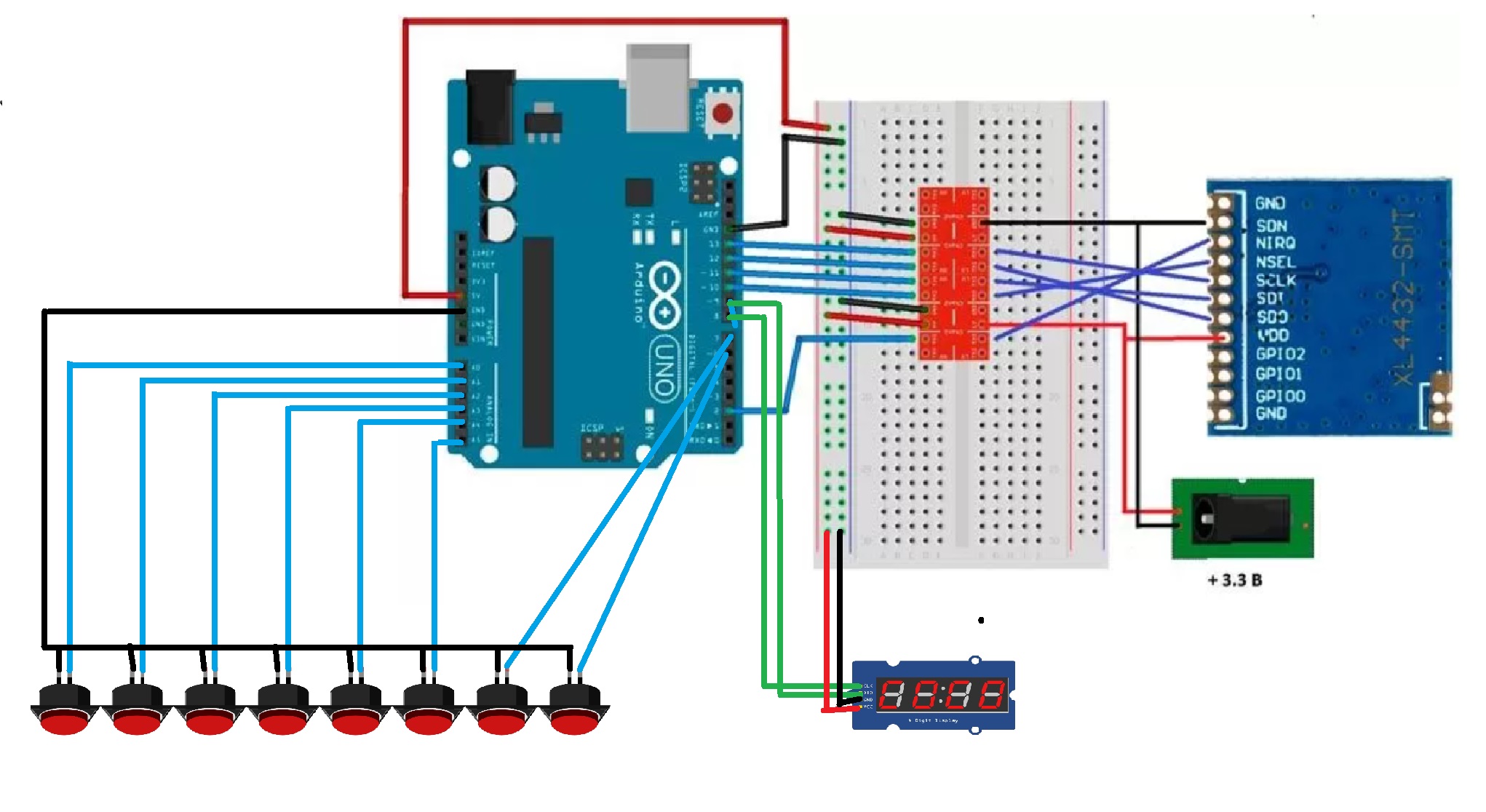
Connection diagrams of elements1) Remote control
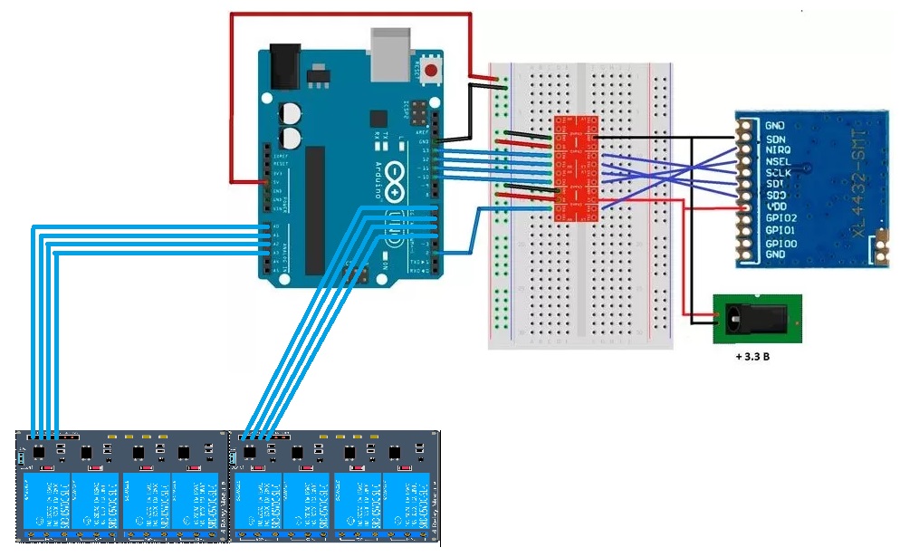
2) executive unit
Sketch for the remote control.
Sketch for the remote control.When the button is pressed, the state of the relay
On the remote control should change. It is stored in an array
uint8_t status_click[]={48, 48, 48, 48, 48, 48, 48, 48}; // 48- off, 49-on
When the button is pressed, the value in the array changes to the opposite. When the button is pressed, as well as every 200 seconds, the remote control sends an array of relay states and waits for confirmation in response - the same array.
The resulting array state is displayed on a display of 4 seven-segment TM1637 indicators
#define YES 0
#define NO 1
#define LED 13
#include <SPI.h>
#include <RF22.h>
#include "TM1637Display.h"
#include <EEPROM.h>
TM1637Display display(8, 9); // CLC, DIO
// for display
const uint8_t n00[] = {
//SEG_D  // _
};
const uint8_t n00_2[] = {
SEG_DP  //SEG_D  // _:
};
const uint8_t n11[] = {
SEG_B | SEG_C |  SEG_E | SEG_F  // |_|
};
const uint8_t n11_2[] = {
SEG_B | SEG_C |  SEG_E | SEG_F | SEG_DP  // |_|:
};
const uint8_t n10[] = {
SEG_E | SEG_F  // |_
};
const uint8_t n10_2[] = {
SEG_E | SEG_F | SEG_DP  // |_
};
const uint8_t n01[] = {
SEG_B | SEG_C  // _|
};
const uint8_t n01_2[] = {
SEG_B | SEG_C | SEG_DP  // _|:
};
const uint8_t err[] = {
SEG_A | SEG_D | SEG_E | SEG_F | SEG_G,            // E
SEG_D ,           // _
SEG_E | SEG_G,           // r
SEG_A | SEG_E | SEG_F | SEG_G            // F
};
const uint8_t err1[] = {
SEG_A | SEG_D | SEG_E | SEG_F | SEG_G,            // E
SEG_D | SEG_DP ,           // _
SEG_E | SEG_G,           // r
SEG_A | SEG_E | SEG_F | SEG_G            // F
};
// buttons pins
//int pinButtons[]={A5,A1,A4,A0,6,A3,7,A2};
int pinButtons[]={A5,A6,A4,A0,6,A3,7,A2};  // bad - A6
int lastButtons[]={NO,NO,NO,NO,NO,NO,NO,NO};
int currentButtons[]={NO,NO,NO,NO,NO,NO,NO,NO};
boolean change=false;
//uint8_t status_click[]={1,1,1,1,1,1,1,1,1,1};
uint8_t status_click[]={48,48,48,48,48,48,48,48};
// Singleton instance of the radio
RF22 rf22;
void(* resetFunc) (void) = 0;
int counterr=0;
unsigned long millist=0;
int cntm=0;
void setup() {
//
Serial.begin(9600);
Serial.println("start");
// ini
if(EEPROM.read(11) != 55)
iniDataEEPROM();
readDataEEPROM();
// buttons
for(int i=0;i<8;i++) {
pinMode(pinButtons[i],INPUT_PULLUP);
}
//
pinMode(LED,OUTPUT);
digitalWrite(LED,LOW);
// display
display.setBrightness(4); // Brightness 0 - 7, true/false
display.clear();
// connect
if (!rf22.init()){
// Defaults after init are 434.0MHz, 0.05MHz AFC pull-in, modulation FSK_Rb2_4Fd36
Serial.println("RF22 init failed");
counterr++;
if(counterr%2==0)
display.setSegments(err);
else
display.setSegments(err1);
delay(500);
if(counterr>5)
resetFunc();
}
delay(200);
display.clear();
digitalWrite(LED,HIGH);
sendrf();
}
void loop()
{
// scan buttons
for(int i=0;i<8;i++) {
currentButtons[i] = debounce(lastButtons[i],pinButtons[i]);
// click...
if (lastButtons[i] == NO && currentButtons[i] == YES) {
;
}
//onclick
else if (lastButtons[i] == YES && currentButtons[i] == NO) {
Serial.print("onclick=");Serial.println(i);
if(status_click[i]==48)
status_click[i]=49;
else
status_click[i]=48;
change=true;
}
lastButtons[i]  = currentButtons[i];
}
// send if change=true
if(change==true) {
sendrf();
}
if((millis()-millist) > 20*1000) {
cntm=(cntm+1)%10;
if(cntm==0){
sendrf();Serial.println(millist);
}
millist=millis();
}
}
The full sketch is attached in the archive for download.
Sketch for the block of actuators
Sketch for the block of actuators#define ON 1
#define OFF 0
#define LED 13
#include <SPI.h>
#include <RF22.h>
// relays pins
//int pinRelays[]={A3,7,A2,6,5,6,A0,4};
int pinRelays[]={A3,7,A2,6,A1,5,A0,4};
uint8_t status_relays[]={0,0,0,0,0,0,0,0};
// Singleton instance of the radio
RF22 rf22;
void(* resetFunc) (void) = 0;
void setup() {
Serial.begin(9600);
// pins relay ini
for(int i=0;i<8;i++) {
pinMode(pinRelays[i],OUTPUT);
digitalWrite(pinRelays[i],OFF);
}
//
pinMode(LED,OUTPUT);
digitalWrite(LED,LOW);
//
if (!rf22.init()){
Serial.println("RF22 init failed");
digitalWrite(LED,HIGH);
// reset
delay(3000);
resetFunc();
}
}
void loop()
{
while (1)
{
rf22.waitAvailable();
//Serial.println(millis());
// Should be a message for us now
//uint8_t buf[RF22_MAX_MESSAGE_LEN];
uint8_t buf[9];
uint8_t len = sizeof(buf);
if (rf22.recv(buf, &len))
{
Serial.println("got request: ");
Serial.println((char*)buf);
// relay
for(int i=7;i>=0;i--){
status_relays[i]=buf[7-i]-48;
Serial.print(status_relays[i]);
}
// on/off
for(int i=0;i<8;i++){
if(status_relays[i]==1)
digitalWrite(pinRelays[i],ON);
else
digitalWrite(pinRelays[i],OFF);
Serial.print("pinRelay ");Serial.print(pinRelays[i]);Serial.print("=");Serial.println(status_relays[i]);
}
//delay(500);
// Send a reply
uint8_t data[9]={0,0,0,0,0,0,0,0,0};
for(int i=0;i<8;i++) {
data[i]=status_relays[i]+48;
}
rf22.send(data, sizeof(data));
rf22.waitPacketSent();
Serial.println("Sent a reply");
}
else
{
Serial.println("recv failed");
}
}
}
The full sketch is attached in the archive for download.


_t9PF3orMPd.png?auto=compress%2Cformat&w=40&h=40&fit=fillmax&bg=fff&dpr=2)


_3u05Tpwasz.png?auto=compress%2Cformat&w=40&h=40&fit=fillmax&bg=fff&dpr=2)
Comments