In this project, we will use a 74HC595 Shift Register IC to drive eight LEDs independently using just three output pins from the Arduino. This will display a binary counter.
What We Will Learn in This Section1. How to connect a 74HC595 Shift Register to an Arduino.
2. How to drive multiple LEDs using fewer Arduino pins.
3. How to write code to control the shift register and display a binary counter.
**Why Is This Lesson Important to You?**This lesson is essential because it demonstrates how to expand the output capabilities of your Arduino using shift registers. It allows you to control multiple outputs, like LEDs, with minimal pin usage, making your projects more efficient.
**Components List**1. Arduino
2. Resistors
3. 5mm LEDs
7. Breadboard
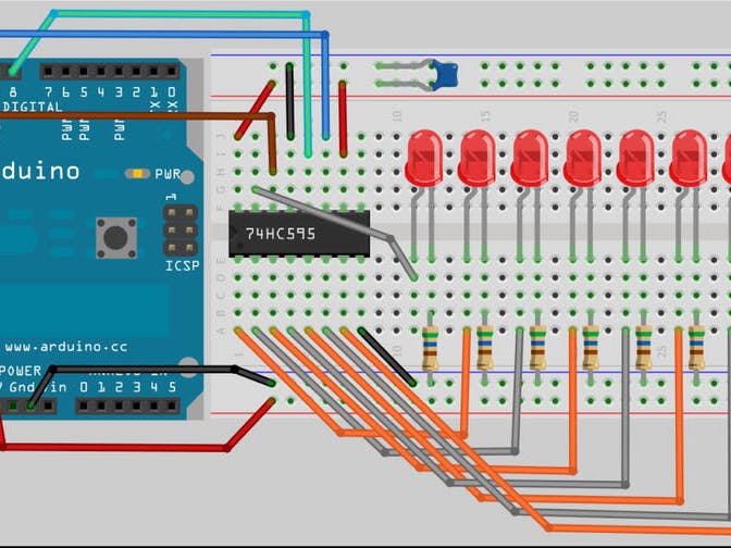
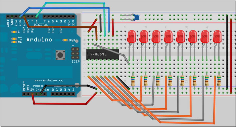
Circuit Diagram (With Connection)Connect the 5V pin of the Arduino to the top rail of your breadboard and the ground (GND) to the bottom rail. The shift register IC should have a small dimple on one end; this dimple goes to the left.
- Pin 1 is below the dimple, pin 8 at the bottom right, pin 9 at the top right, and pin 16 at the top left.
- Connect the 5V supply to pins 10 and 16 of the IC.
- Connect the ground (GND) to pins 8 and 13 of the IC.
- Connect a wire from digital pin 8 of the Arduino to pin 12 of the IC.
- Connect a wire from digital pin 12 of the Arduino to pin 11 of the IC.
- Connect a wire from digital pin 11 of the Arduino to pin 14 of the IC.
- The anode of LED 1 goes to pin 15, and the anodes of LEDs 2 to 8 go to pins 1 to 7 of the IC.
- Place a 560Ω resistor between the cathode of each LED and ground.
- Use a 0.1uF decoupling capacitor between the power supply pin and the ground, keeping the leads short and the capacitor close to the chip.
**Code**int latchPin = 8; // Pin connected to Pin 12 of 74HC595 (Latch)
int clockPin = 12; // Pin connected to Pin 11 of 74HC595 (Clock)
int dataPin = 11; // Pin connected to Pin 14 of 74HC595 (Data)
void setup() {
// Set pins to output
pinMode(latchPin, OUTPUT);
pinMode(clockPin, OUTPUT);
pinMode(dataPin, OUTPUT);
}
void loop() {
// Count from 0 to 255
for (int i = 0; i < 256; i++) {
shiftDataOut(i);
// Set latchPin low then high to send data out
digitalWrite(latchPin, LOW);
digitalWrite(latchPin, HIGH);
delay(1000);
}
}
void shiftDataOut(byte dataOut) {
// Shift out 8 bits LSB first, clocking each with a rising edge of the clock line
for (int i = 0; i <= 7; i++) {
digitalWrite(clockPin, LOW); // Set clockPin to LOW prior to sending bit
// If the value of dataOut and a bitmask are true, set pinState to HIGH
boolean pinState = dataOut & (1 << i) ? HIGH : LOW;
// Set dataPin to HIGH or LOW depending on pinState
digitalWrite(dataPin, pinState); // Send bit out before rising edge of clock
digitalWrite(clockPin, HIGH);
}
digitalWrite(clockPin, LOW); // Stop shifting out data
}Initialization:
latchPin,clockPin, anddataPinare set to the respective pins connected to the 74HC595.- The
setup()function sets these pins as output. - Initialization:
latchPin,clockPin, anddataPinare set to the respective pins connected to the 74HC595.
Thesetup()function sets these pins as output.
Main Loop:
- The
loop()function counts from 0 to 255. - For each count, it calls
shiftDataOut(i)to send the data to the shift register. - The
latchPinis toggled low and then high to latch the data, making it available on the output pins. - A delay of 1 second is added between counts.
- Main Loop:
Theloop()function counts from 0 to 255.
For each count, it callsshiftDataOut(i)to send the data to the shift register.
ThelatchPinis toggled low and then high to latch the data, making it available on the output pins.
A delay of 1 second is added between counts.
Shifting Data Out:
- The
shiftDataOut()function shifts out 8 bits of data, one bit at a time. - For each bit, it sets the
clockPinlow. - It checks if the corresponding bit in
dataOutis high or low and sets thedataPinaccordingly. - It then sets the
clockPinhigh to clock the bit into the shift register. - Finally, it sets the
clockPinlow to stop shifting data. - Shifting Data Out:
TheshiftDataOut()function shifts out 8 bits of data, one bit at a time.
For each bit, it sets theclockPinlow.
It checks if the corresponding bit indataOutis high or low and sets thedataPinaccordingly.
It then sets theclockPinhigh to clock the bit into the shift register.
Finally, it sets theclockPinlow to stop shifting data.
Ensure that all connections are secure and the LEDs are connected correctly. The decoupling capacitor is crucial to reduce electrical noise and ensure stable operation of the circuit. Once everything is set up, upload the code to your Arduino, and you should see the LEDs displaying a binary counter.


_ztBMuBhMHo.jpg?auto=compress%2Cformat&w=48&h=48&fit=fill&bg=ffffff)


Comments
Please log in or sign up to comment.