


In this project, we will interface a Nintendo DS touch screen with an Arduino using a touch screen breakout module. This setup will allow you to detect touch inputs and display the coordinates on the serial monitor.
Required Components
1. Arduino
2. Resistors
4. Touch Screen Breakout Module
6. Breadboard
**Note:** The touch screen breakout module is essential as it facilitates the connection between the touch screen’s fragile ribbon connector and the Arduino.
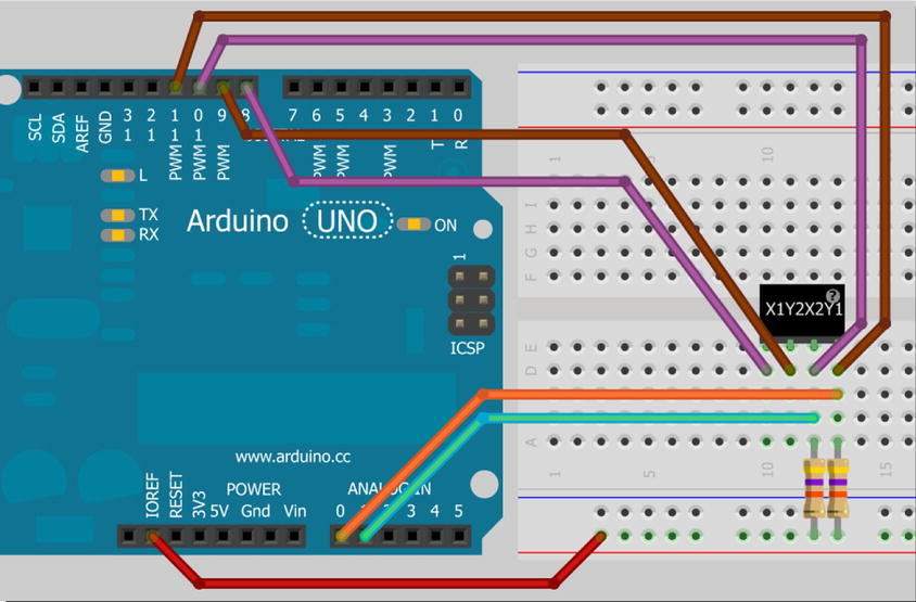
Circuit Diagram and Connections
The breakout module has pins labeled X1, Y2, X2, and Y1. The connections are as follows:
- - **X1 (Left)**: Connect to digital pin 8
- - **Y2 (Bottom)**: Connect to digital pin 9
- - **X2 (Right)**: Connect to digital pin 10
- - **Y1 (Top)**: Connect to digital pin 11
Additional setup:
- Connect IOREF (or 5V for older Arduino boards) to the breadboard.
- Use high-value resistors (around 50K ohms) between X2 and Y1 pins and the IOREF line on the breadboard.
To solder header pins to the breakout module:
- Ensure the SparkFun logo faces upward.
- Connect the screen to the breakout module using the small connector, with the ribbon connector positioned at the top right.
Code
// Power connections
#define Left 8 // Left (X1) to digital pin 8
#define Bottom 9 // Bottom (Y2) to digital pin 9
#define Right 10 // Right (X2) to digital pin 10
#define Top 11 // Top (Y1) to digital pin 11
// Analog connections
#define topInput A0 // Top (Y1) to analog pin A0
#define rightInput A1 // Right (X2) to analog pin A1
int coordX = 0, coordY = 0;
void setup() {
Serial.begin(38400);
}
void loop() {
if (touch()) { // If screen touched, print coordinates
Serial.print(coordX);
Serial.print(" ");
Serial.println(coordY);
delay(250);
}
}
boolean touch() {
boolean touch = false;
// Get horizontal coordinates
pinMode(Top, INPUT); // Top and Bottom to high impedance
pinMode(Bottom, INPUT);
pinMode(Left, OUTPUT);
digitalWrite(Left, LOW); // Set Left to low
pinMode(Right, OUTPUT); // Set Right to +5V
digitalWrite(Right, HIGH);
delay(3);
coordX = analogRead(topInput);
// Get vertical coordinates
pinMode(Right, INPUT); // Left and Right to high impedance
pinMode(Left, INPUT);
pinMode(Bottom, OUTPUT); // Set Bottom to Gnd
digitalWrite(Bottom, LOW);
pinMode(Top, OUTPUT); // Set Top to +5V
digitalWrite(Top, HIGH);
delay(3);
coordY = analogRead(rightInput);
// Check if the screen has been touched
if (coordX < 1000 && coordX > 24 && coordY < 1000 && coordY > 24) {
touch = true;
}
return touch;
}
Instructions
1. **Connection Setup**: Connect the touch screen and breakout module to the Arduino as per the circuit diagram.
2. **Upload Code**: Upload the provided code to your Arduino.
3. **Open Serial Monitor**: Set the baud rate to 38400.
4. **Touch Detection**: Touch the screen. The coordinates of your touch will be displayed on the serial monitor.
Calibration
To ensure accurate touch detection, you might need to calibrate the touch screen. Adjust the connections and verify the touch coordinates to ensure they align correctly with your touch input.
Additional Tips
- **Handling**: The touch screen and breakout module are fragile. Fix them securely to the breadboard to prevent movement and potential damage.
- **Heat Shrink Tubing**: If you use heat shrink tubing for waterproofing, opt for dual-wall or filled-core types for better protection.
Conclusion
By following this guide, you can successfully interface a Nintendo DS touch screen with an Arduino, allowing you to detect touch inputs and display the coordinates on the serial monitor. This project is an excellent way to explore the basics of touch screen technology and Arduino interfacing.
For more detailed information and advanced projects, consider referring to the book **"Beginning Arduino."**
---
This guide provides a comprehensive overview of setting up a basic touch screen interface with Arduino, covering the required components, circuit diagram, and step-by-step instructions for code implementation and touch detection.

Comments
Please log in or sign up to comment.