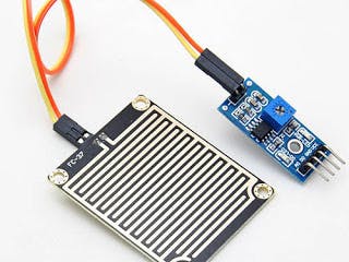
In this tutorial, we delve into the fascinating world of raindrop sensors and their integration with NodeMCU. Raindrop sensors are versatile tools that can detect raindrops falling on their surface, enabling applications ranging from simple rain detection to measuring rainfall intensity.
What You Will Learn in This Section- Understanding the working principle of raindrop sensors
- Connecting a raindrop sensor module to NodeMCU
- Programming NodeMCU with Arduino to read and respond to raindrop sensor data
Learning to interface raindrop sensors with NodeMCU opens up opportunities for weather monitoring, automated irrigation systems, and more. It's a crucial skill for anyone interested in IoT and smart home projects.
Components List- NodeMCU
- Raindrop Sensor Module
- Jumper wires
- Breadboard
- Power supply (5V)
- Resistors (as needed for level shifting)
The raindrop sensor consists of a black board with nickel-coated traces. It operates on the principle of resistance: when raindrops bridge these traces, the sensor's resistance decreases, altering the voltage across it. This change is detected by NodeMCU to determine the presence and intensity of rainfall.
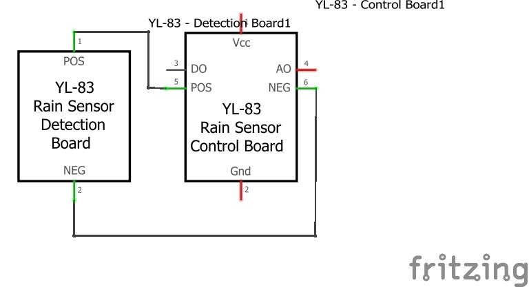
Circuit Diagram of Raindrop Sensor Interfacing with NodeMCU- NodeMCU A0 to Raindrop Sensor Analog Output
- NodeMCU GND to Raindrop Sensor GND
- NodeMCU 3.3V to Raindrop Sensor VCC
#include <ESP8266WiFi.h>

const char* ssid = "your_wifi_ssid";
const char* password = "your_wifi_password";

WiFiClient client;

int sensorPin = A0;
int enablePin = D7; // Adjust as per your setup
int sensorValue = 0;

void setup() {
  pinMode(enablePin, OUTPUT);
  Serial.begin(115200);
  delay(10);

  WiFi.begin(ssid, password);
  Serial.println();
  Serial.println("Connecting to WiFi...");

  while (WiFi.status() != WL_CONNECTED) {
    delay(500);
    Serial.print(".");
  }

  Serial.println("");
  Serial.println("WiFi connected");
}

void loop() {
  sensorValue = analogRead(sensorPin);

  // Adjust sensorValue range based on your sensor calibration
  sensorValue = constrain(sensorValue, 150, 440);
  sensorValue = map(sensorValue, 150, 440, 1023, 0);

  if (sensorValue >= 20) {
    Serial.println("Rain detected");
    digitalWrite(enablePin, HIGH);
  } else {
    Serial.println("No rain detected");
    digitalWrite(enablePin, LOW);
  }

  delay(1000); // Adjust delay as needed
}
- sensorPin = A0: Defines the pin connected to the raindrop sensor's analog output.
- enablePin = D7: Configures D7 (or any digital pin) to enable reading from the raindrop sensor.
- analogRead(sensorPin): Reads analog input from the raindrop sensor.
- digitalWrite(enablePin, HIGH/LOW): Controls the enable pin based on rain detection.
python
Copy code
import machine
import time

sensor_pin = machine.A0
enable_pin = machine.Pin(13, machine.Pin.OUT)  # Adjust pin as per your setup

def connect_wifi(ssid, password):
    import network
    wlan = network.WLAN(network.STA_IF)
    wlan.active(True)
    wlan.connect(ssid, password)
    while not wlan.isconnected():
        pass
    print("WiFi connected")

def read_sensor():
    sensor_value = sensor_pin.read()

    # Adjust sensor value range based on calibration
    sensor_value = sensor_value if 150 <= sensor_value <= 440 else 1023

    return sensor_value

def main():
    connect_wifi("your_wifi_ssid", "your_wifi_password")

    while True:
        sensor_value = read_sensor()

        if sensor_value >= 20:
            print("Rain detected")
            enable_pin.on()
        else:
            print("No rain detected")
            enable_pin.off()

        time.sleep(1)  # Adjust delay as needed

if __name__ == "__main__":
    main()
- sensor_pin = machine.A0: Defines the pin connected to the raindrop sensor's analog output.
- enable_pin = machine.Pin(13, machine.Pin.OUT): Configures pin 13 (or any digital pin) as output to enable reading from the raindrop sensor.
- sensor_pin.read(): Reads analog input from the raindrop sensor.
- enable_pin.on() and enable_pin.off(): Controls the enable pin based on rain detection.
Interfacing a raindrop sensor with NodeMCU using MicroPython enables efficient rain detection and integration into IoT applications. Experiment with different sensor placements and sensitivity levels to optimize performance for your projects.
1.Intoduction to nodemcu8266 & Steps to Import ESP Board Libraries 2.NodeMCU8266 Basic Project-Blink a LED
3.NodeMCU8266 Digital Read (Push Button)
4.Analog Data read using NodeMcu8266
5. NodeMcu LED control Use in Blynk app in IOT platform
6.NodeMcu to DHT Interface in Blynk app| On IOT Platform
7.The Best Way To nodemcu gps tracker blynk app |in IOT platform
8. NodeMCU RGB LED | For beginners
9.Servo Control With NodeMCU and Blynk | In IOT Platform


Comments
Please log in or sign up to comment.