First of all, these are not ideas of mine. I just wanted to pack them all in one project, polish it up a bit, and publish it. I wanted to let Due owners know that there are features on this board that they may not know about; some of these features can be obtained with external cheap peripherals.
If you don't feel "ice bold" with micro-soldering or you want avoid risking your Due, DON'T MODIFY YOUR BOARD!!!
Subjects covered here:
- MOSFET bug on V02 boards
- Absence of slow quartz on phony boards
- VDDBU mod
- NRST mod
- ATMega16u2 functionalities\mod
- Overclock
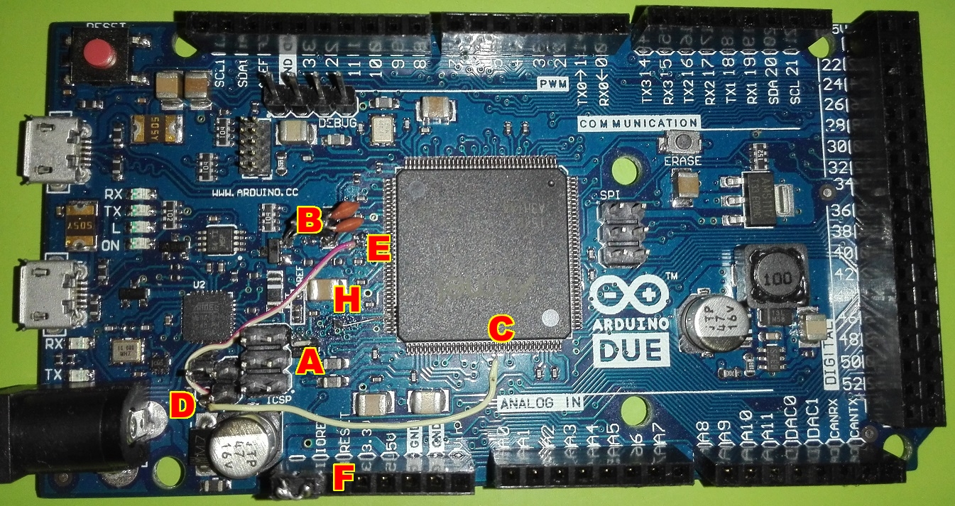
The V02 board is distinguishable from the newer V03 by the orientation of the MOSFET depicted below. If the two pins on the same side of the MOSFET (gate and source) point to Pin 13 of the board, it's a V02, otherwise it's a V03.
==MOSFET Resister ModMy board is the elder one, called V02. Mine is actually a counterfeit, the V02 board suffers from random mis-boots and it hangs at boot sometimes. This is due to the fact that the MOSFET that pulls up the erase pin of the sam3x8e have its gate briefly left floating during the ATMega16u2 startup, actually randomizing the MOSFET closing. This lasts very briefly, not enough to erase the MCU but it can "go crazy." The solution is to put a 10k (2k7 works as well) resistor across the gate and the source of the MOSFET, letting it stay off if left undriven.
Counterfeits or maybe clones usually don't have the 32'768Hz quartz. This crystal is not necessary almost for anything, but it can be used for letting the onboard RTC of the sam3x8e run, or to have a slower clock source, or to let the "Real Time Timer" run at precise speed (unlike with the on-chip RC oscillator). There's also a neat library for the RTC if you don't want to go crazy over the 1500 pages datasheet of the sam3x8e. You should fit a watch crystal with possibly a known capacitance load of 12.5pF. This component can be found in every classic "el cheapo" clock. This kind of crystal has a better stability than lower capacitance ones, and is easily available on the market. Along with the crystal of 12.5pF, you must fit two small capacitance caps from the two crystal pads to a suitable GND spot. They must be of around 18pF each.
Soldering the crystal case is a bad practice, but it will avoid potential noise. Scratch the spot of the case that you want to tin with a cutter, and be fast at soldering. Don't let it heat up "supernova style," and maybe assemble the three components before placing them on the board.
==The VDDBU ModTo use this mod you need the NRST mod also.
The Due isn't intended to be put to sleep, you should power it or turn it completely off, but sleep features as well as "semi-powered" features are present on the sam3x8e, like the "Backup Domain". The main MCU has a VDDBU pin (number *52 of the chip) that can be supplied with 3V from a small battery (CR2032 ?) to let some internal peripherals stay powered, even if there's no VCC supplied, these peripherals are:
- RTC (time, calendar, a bunch of alarms\interrupts\wakeups)
- GPBRs (eight 32bit NVRAM General Purpose Backup Registers for your settings and stuff)
- RTT (Real Time Timer; actually a 32bit counter with some interrupts)
- SUPC (Supply Controller; we don't care)
To be able to connect a battery to this pin, we must first isolate it from the 3.3V net. The track to cut looks different from V02 to V03, but it's basically the same. You must cut the pits near the chip, because there are other components connected to the 3.3V line; but you must leave a portion of track to be able to solder a thin wire (to avoid soldering on the MCU pin).
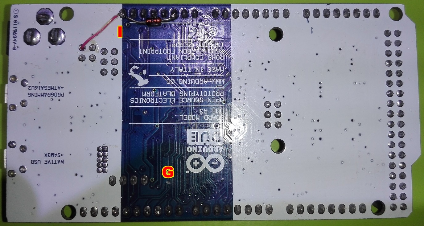
Then our wire can take a tour on the board, pass through a hole and be connected to the "spare" pin near IOREF. I've also added a Zener, pointing from GND to VDDBU, to avoid discharges on the "micropower" pin. I've used an around 6V one that at 4V draws 1uA.
The VDDBU pin will constantly draw 2-4uA from the battery, plus leaks, this will let the RTC run on a CR2032 for years.
If you are questioning yourself about where to find those super-thin wires, just use a PATA IDE hard drive cable, the type used after 1998 (thinner wires).
I don't suggest to place caps in parallel or "twin Y" schottky diodes in series, because this is discouraged by RTC manufacturers. Instead, I used a Dupont male jumper from IOREF to VDDBU in case I don't want to "backup", this is needed because if you don't power the VDDBU pin the board will not work.
The GPBRs are offensively easy to use.
uint32_t a = 0xFFFFFFFF;
uint32_t z = GPBR->SYS_GPBR[i];
GPBR->SYS_GPBR[i] = a;
"i" is from 0 to 7. That's it, just like variables.
The RTC can be used with the RTCDue library. The RTT, I don't know, these are general pourpose features; read the datasheet. :)
==The NRST ModIf you make just the VDDBU mod, you'll come up with a problem. The 16u2 will reset the sam3x with every excuse; for doing so, it will assert low the NRSTB pin (pin *47 of the chip); with this it will reset ANYTHING on the sam3x8e except the flash. There's another reset pin on the package (yes, more than one), the NRST (pin *69); this reset pin doesn't touch the backup domain, so the VDDBU mod makes sense now. You need to cut the line that leads to NRSTB.
Then connect the reset net to NRST. I did it through a 2k2 resistor, but I thought that there was a 1k resistor from the 16u2 to the reset net, but it's instead 10k. The possible pull-down made by NRST will not cause a problem if you don't fit a resistor (NRST pull-down is capable of little current), however, you may fit another 2k7 resistor.
Beware that when uploading with the programming port, the sketch will not reboot on its own if you use NRST. You need to repower the board (or mod leaving the reset track to NRSTB still leading to the button and press it after upload).==The ATMega16u2 "Awakening" Mod
Why use the ATMega16u2 just for uploading and serial monitor when it's a microcontroller on its own? It can be used, for example, as GPIO or for its EEPROM, feature that the sam3x8e doesn't have.
We'll gain three features directly on the sketch loaded on the sam3x8e:
- Read and write the 512 bytes EEPROM on the 16u2
- Use 6 of its GPIOs (the good ol' 20-40mA 5V pins like the Uno board)
- Disable\re-enable auto-reset on programming port
The software used here was taken online and heavily modified to my preferences. For example, you now don't need to disable the system in case it's not used or you don't need to open serial monitor to let the two chips communicate. The "GPIO" and "autoreset" features were added.
This system isn't "bombproof," but it should work well if you don't stress it too much with speed. Also, consider it in "beta" stage.
Hardware ModFirst let's take a look at the hardware mod. The sam3x8e must say to the 16u2 to listen on the "Serial" port for particular instructions, for doing so an "assert" wire must be fitted. The cleanest way is to solder a wire from an unused pin on the sam3x8e to the header pad near the 16u2, but a standard pin can also be used if you don't want to microsolder the sam3x, but you'll have a wire hanging around.
This uses pin *93 (PC11):
Then it goes to PB7 of the 16u2 (this pin is hardcoded in the new firmware for this task), it's better to fit a resistor to avoid pin conflicts, let's say 2k7 (again).
I've used the PB7 pad for both passing the VDDBU wire and 16u2 asserting, cool uh? :)
Software ModThen the software part of the mod. You need a way to program the 16u2. There are different ways, all documented online. I've used an USBasp programmer, but you'll have a big whoop of problems for installing drivers on Win10 (you must disable driver signature check at boot). Burn the modified firmware provided here on the 16u2, place the library into the IDE and now you are ready to go (read examples first).
This mod is annoyance free, it means that you can happily forget about it and use your Due as usual.
==OverclockOverclock is possible and quite easy to perform, it's just a reconfiguration to add on top of the sketch:
#define SYS_BOARD_PLLAR (CKGR_PLLAR_ONE | CKGR_PLLAR_MULA(18UL) | CKGR_PLLAR_PLLACOUNT(0x3fUL) | CKGR_PLLAR_DIVA(1UL))
#define SYS_BOARD_MCKR ( PMC_MCKR_PRES_CLK_2 | PMC_MCKR_CSS_PLLA_CLK)
//Set FWS according to SYS_BOARD_MCKR configuration
EFC0->EEFC_FMR = EEFC_FMR_FWS(4); //4 waitstate flash access
EFC1->EEFC_FMR = EEFC_FMR_FWS(4);
// Initialize PLLA to 114MHz
PMC->CKGR_PLLAR = SYS_BOARD_PLLAR;
while (!(PMC->PMC_SR & PMC_SR_LOCKA)) {}
PMC->PMC_MCKR = SYS_BOARD_MCKR;
while (!(PMC->PMC_SR & PMC_SR_MCKRDY)) {}
// Re-initialize some stuff with the new speed
SystemCoreClockUpdate();
On the first line there's "18UL," this tells the PLL what multiplier value to use, "13UL" is stock speed.
Is this useful? Probably not because the power of microcontrollers derives from their functionalities and not (much) from their speed.


Comments
Please log in or sign up to comment.