INTRODUCTION
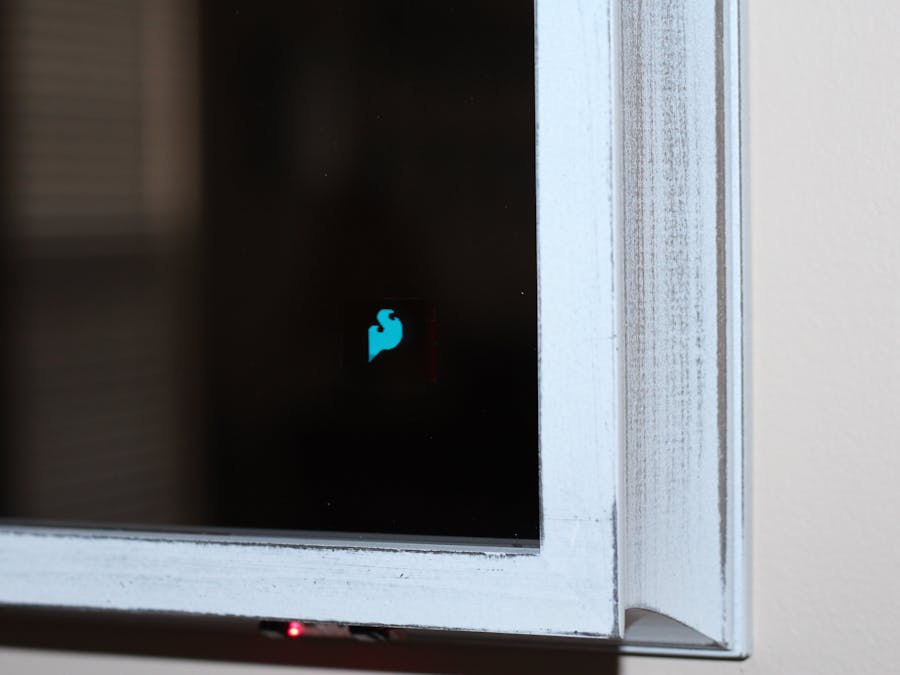
My routine just before I leave the house each day involves the same three things: check the weather outside, check my appearance in the mirror, and check my commute time. I want to accomplish all of the above steps as quickly as possible and not have to rely on using multiple mobile phone apps. So I built an intelligent mirror that displays local atmospheric conditions and the estimated drive time to work/school/etc with real-time traffic info. The finished project is shown in the image below.
The intelligent mirror in this project is constructed from a semi-transparent (i.e. one-way) glass mirror housed in a shadow box that has two micro-OLED breakouts positioned behind it, which are visible to anyone looking at the mirror. There is one atmospheric sensor on the mirror frame to measure the local (indoor) temperature and humidity and additional atmospheric sensors located remotely (outdoor) to measure temperature, pressure, barometric pressure, total volatile organic compounds (TVOCs) and equivalent carbon dioxide (CO2) levels. Behind the mirror there is also a proximity sensor, which could be used to turn ON/OFF the OLED displays when it detects a person standing in front of the mirror.
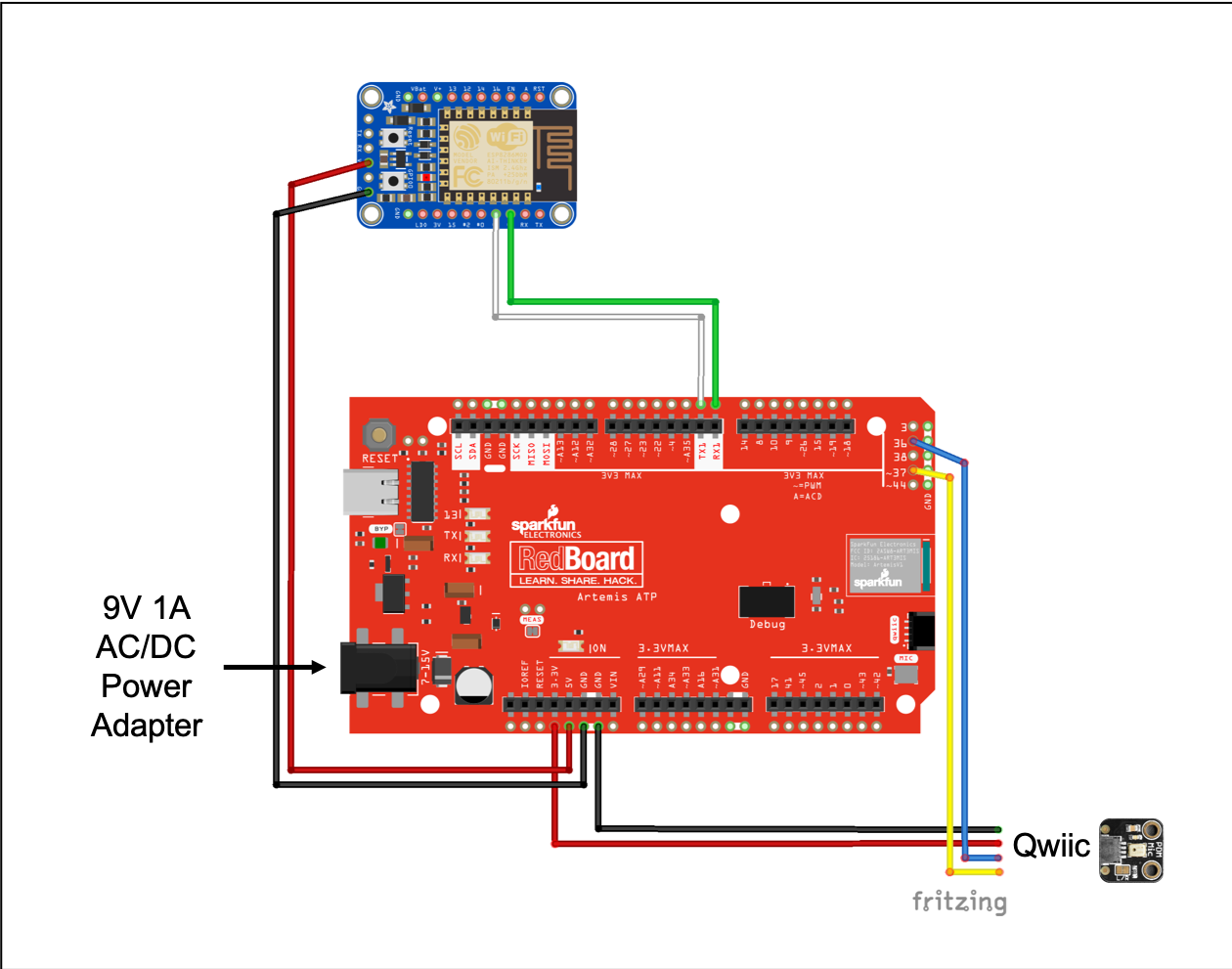
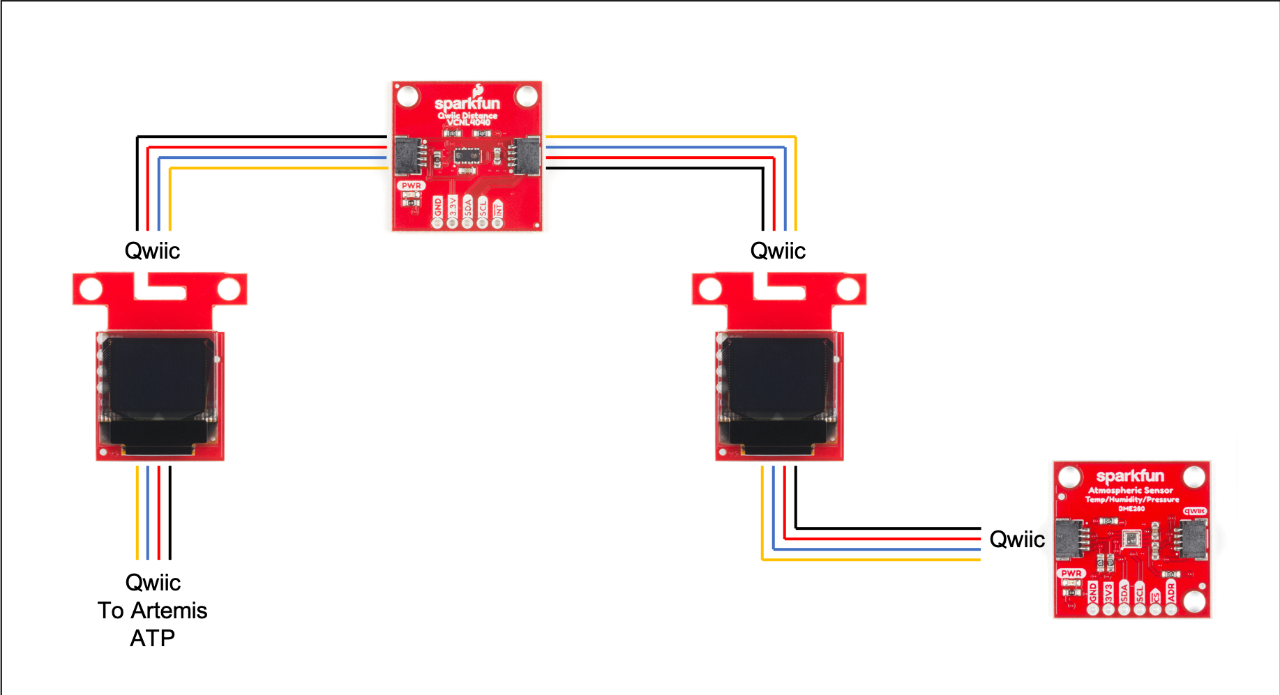
The SparkFun RedBoard Artemis ATP is directly connected to the OLED displays, proximity sensor, and the indoor atmospheric sensor breakout via Qwiic cables. An ESP8266 HUZZAH breakout connected to the Artemis ATP at the mirror will allow the board to connect to the Internet to access Google Maps information. The environmental combo breakout, which is separate from the mirror and is located outdoors, is connected to a Adafruit ESP8266 HUZZAH breakout and communicates with the Artemis ATP via wifi.
My plan was to use the machine learning capabilities of the Artemis chip and the built-in microphone of the Artemis ATP to perform speech recognition. I used the TensorFlow micro speech example as a framework for creating a model to recognize words such as "work" or "school" to get traffic and drive time info interactively. Unfortunately, I ran out of time training the model and was not able to get it to recognize the audio commands for this project. As a workaround, I used the Google Maps Distance Matrix API to return the drive time and distances for multiple destinations simultaneously. I programmed the Artemis ATP to scroll through the Google Maps results for driving to each destination on the OLED displays.
THE BUILD
The first step in building this project was to remove the glass pane from the shadow box. After removing the back panel of the shadow box, I noticed that there were some thin wooden strips on the interior of the frame that held the glass in place. I easily removed them using a pry bar (see photo below). I ended up using one of the strips as a spacer in a later step so it is a good idea to set these aside instead of throwing them in the trash.
Unfortunately, the shadow box frame measured slightly smaller than 12 in. x 12 in. so the see-through glass mirror that I purchased would not fit like I had hoped. There was no chance I was going to try to cut the glass down to size, so instead, I cut a slot in the wooden frame. I used a rotary tool (Dremel) to cut away a strip of wood from the frame to allow the mirror to fit in place:
I found that pulling on the sides of the shadow box frame helped expand the opening just enough to help get the glass into position. Before pushing the mirror into its position, it's important to make sure to note the side that is more reflective and orient it so that it is facing towards the observer. Once the glass goes into position, it will be very difficult to remove.
Next, I arranged the OLED displays, proximity sensor, and Qwiic cables on a 12 in. x 12 in. piece of cardboard that will mount to the back of the see-through mirror. I secured the sensors to the cardboard using tape. Here is the step where I used one of the wooden strips that were removed from the shadow box. I glued a strip to the top of the cardboard to provide a uniform space between the cardboard and the glass mirror.
Then I covered the cardboard and sensors with black fabric and carefully cut holes in the fabric around the OLED displays and the proximity sensor with a hobby knive (x-acto).
I secured the fabric to the cardboard using tape and created a handle on the back to make removing the cardboard from the shadow box easier. I cut opening in the fabric to allow the Qwiic cables to pass through. One of the cables will connect to the Artemis ATP and the other is connected to the BME280 atmospheric sensor.
The original back panel of the shadow box was used for mounting the Artemis ATP and HUZZAH ESP8266. I drilled small holes in the back panel and used zip ties to secure the HUZZAH and power cord in place. I used nylon M3 screws to secure the Artemis ATP in position. I also cut small notches at the bottom of the back panel to easily pass the Qwiic cable of the microphone and power cord through the back of the shadow box.
Next, I used my drill to make some holes for the wires to pass through the wooden frame. I made three holes at the bottom of the frame - for the BME280 sensor, for the microphone, and a notch for the power cord.
After drilling the holes, it was time to connect the sensors, which are secured to the cardboard and covered in black fabric, to the Artemis ATP board.
Choosing a long Qwiic cable (500mm) for connecting the two panels makes assembly and disassembly easier. The extra slack is helpful for when you need to pull off the back panel. The Arduino sketch was uploaded to the Artemis ATP using the USB cable.
After passing the Qwiic connectors through the wooden frame, the mirror was ready for the final assembly. Just bend the metal tabs over the back panel to hold it in place. I used foam mounting tape to secure the BME280 sensor and microphone to the bottom of the wooden frame.
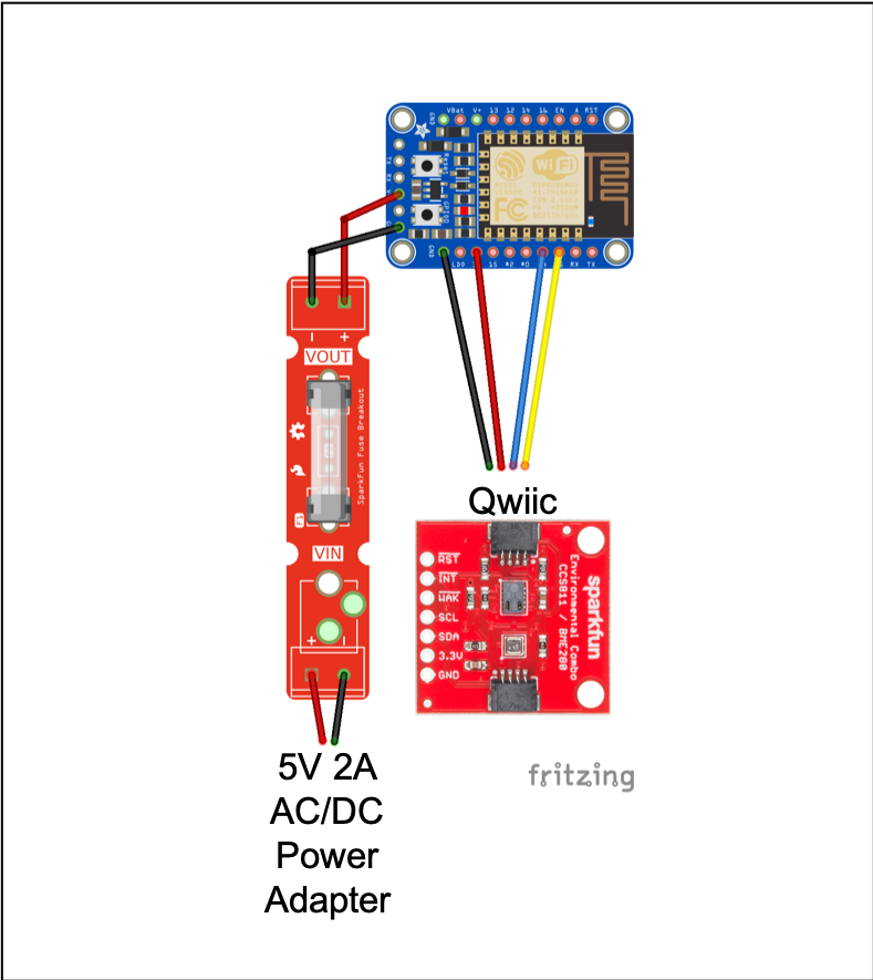
After completing the assembly of the mirror, it is time to build the remote weather station. The weather station is simply a HUZZAH ESP8266 connected to the CCS811/BME280 environmental combo breakout. The first step is to prepare the weather enclosure and 5V power adapter. The barrel jack would not fit through the cable gland so I cut the power cord to remove it and stripped the wire leads.
The enclosure is weatherproof but I added a SparkFun fuse breakout with a 500 mA fuse inside the enclosure just to be safe. Then I added the remaining components and connected them together using jumper wires.
I passed a Qwiic cable through the other cable gland and connected the CCS811/BME280 environmental sensor. All that remains is to upload the code to the HUZZAH ESP8266 using the USB to TTL serial cable and secure the cover of the enclosure to the base. I mounted the remote weather station to a 4 in. x 4 in. wood post on my porch near a power outlet. After powering ON the weather server, it was time to hang the mirror.


Comments
Please log in or sign up to comment.