


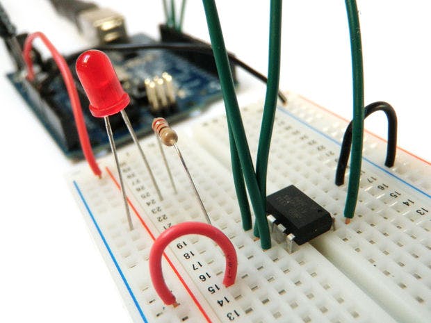
Hardware components | ||||||
_ztBMuBhMHo.jpg?auto=compress%2Cformat&w=48&h=48&fit=fill&bg=ffffff) |
| × | 1 | |||
The VCNL4000 is a proximity sensor with an integrated ambient light sensor. It is the industry’s first optical sensor to combine an infrared emitter, PIN photodiode, ambient light sensor and signal processing in a single package with a 16-bit ADC for proximity measurement as well as ambient light measurement.
VCNL4000 is designed specifically for the low height requirements of smart phone, mobile phone, digital camera, and tablet PC applications.Through its standard I2C bus serial digital interface, it allows easy access to a “Proximity Signal” and “Light intensity” measurement without complex calculations or programming (also, this sensor has inside it IIR filter). First, I am going to tell about I2C protocol that this sensor uses to communicate with MCU.
This sensor is easy to use with any microcontroller that has i2c capability. It is 5 volt compliant so you can use it with 3.3V or 5V logic with no risk of damage. There is an onboard 3.3V ultra low dropout regulator so you can power it with 3.3 to 5.0V. However, if you can give it 5.0V that is ideal since the VIN voltage powers the IR LED and the higher the voltage you can give it, the more powerful it is. Also, this sensor is „Digitally Addressable Sensor“ with IIR filter inside which does all the „magic“ for you, so you do not need measure characteristic and linearise it in its working area like for analog sensors do. That means VCNL4000 does not have a analog output, but instead outputs a 16bit digital reading that will be „shown“ on MCU.
An Inter-IC bus is often used to communicate across circuit-board distances. Here’s a primer on the protocol.
Philips originally developed I2C for communication between devices inside of a TV set. Examples of simple I2C-compatible devices found in embedded systems include EEPROMs, thermal sensors, and real-time clocks. I2C is also used as a control interface to signal processing devices that have separate, application-specific data interfaces. For instance, it’s commonly used in multimedia applications, where typical devices include RF tuners, video decoders and encoders, and audio processors. In all, Philips, National Semiconductor, Xicor, Siemens, and other manufacturers offer hundreds of I2C-compatible devices. With I2C you can chain „only“ upto 128 devices/sensors. Using I2C you can set individual address locations for various sensors..
I2C uses just two wires to implement serial communication between one or more master devices and one or more slave devices. Communication is initiated with a START bit (Which is a START condition generated by bringing SDA low while CLK is high) and then is followed with a Control Byte. The control byte consists of the control code, device address, and the read/write bit.
SCL is the clock line. It is used to synchronize all data transfers over the I2C bus. SDA is the data line. The SCL & SDA lines are connected to all devices on the I2C bus. There needs to be a third wire which is just the ground or 0 volts. There may also be a 5volt wire is power is being distributed to the devices. Both SCL and SDA lines are “open drain” drivers. What this means is that the chip can drive its output low, but it cannot drive it high. For the line to be able to go high you must provide pull-up resistors to the 5v supply.
There are both 7- and 8-bit versions of I2C addresses. 7 bits identify the device, and the eighth bit determines if it’s being written to or read from. The Wire library uses 7 bit addresses throughout. If you have a datasheet or sample code that uses 8 bit address, you’ll want to drop the low bit (i.e. shift the value one bit to the right), yielding an address between 0 and 127.
The first thing that will happen is that the master will send out a start sequence. This will alert all the slave devices on the bus that a transaction is starting and they should listen in incase it is for them. Next the master will send out the device address. The slave that matches this address will continue with the transaction, any others will ignore the rest of this transaction and wait for the next. Having addressed the slave device the master must now send out the internal location or register number inside the slave that it wishes to write to or read from. This number is obviously dependant on what the slave actually is and how many internal registers it has. Some very simple devices do not have any, but most do, including all of our modules. Our CMPS03 has 16 locations numbered 0-15. The SRF08 has 36. Having sent the I2C address and the internal register address the master can now send the data byte (or bytes, it doesn’t have to be just one). The master can continue to send data bytes to the slave and these will normally be placed in the following registers because the slave will automatically increment the internal register address after each byte. When the master has finished writing all data to the slave, it sends a stop sequence which completes the transaction. So to write to a slave device:
1. Send a start sequence
2. Send the I2C address of the slave with the R/W bit low (even address)
3. Send the internal register number you want to write to
4. Send the data byte
5. [Optionally, send any further data bytes]
6. Send the stop sequence.
Reading from the Slave
This is a bit more complicated - but not too much. Before reading data from the slave device, you must tell it which of its internal addresses you want to read. So a read of the slave actually starts off by writing to it. This is the same as when you want to write to it: You send the start sequence, the I2C address of the slave with the R/W bit low (even address) and the internal register number you want to write to. Now you send another start sequence (sometimes called a restart) and the I2C address again - this time with the read bit set. You then read as many data bytes as you wish and terminate the transaction with a stop sequence.
Now I am going to implement this on arduino, because of its API simplicity. Arduino uses wire.h library, and this library allows you to communicate with I2C / TWI devices. Arduino Uno uses A4 (SDA), and A5 (SCL) pins for I2C.
First, you should rad VCNL4000 data sheet to see registers which this sensor uses. It is available here. In page 6 there is a simple, understandable flowchart for proximity sensing and this is a start-off for our algorithm implementation.
Wiring the sensor
I already said that VCNL4000 is an I2C device. I2C is a 2-wire serial connection, so you just need to connect the SDA (Data) and SCL (Clock) lines to your Arduino for communication. On most arduinos SDA is on analog pin A4, and SCL is on analog pin A5. On an arduino mega, SDA is digital 20, and SCL is digital 21. The Leonardo’s have their own special connections.
The board needs 3.3v to run, but it also needs 5V for the IR led that it uses to check the proximity.
So to wire this sensor with arduino, connect (the right side is Arduino connectors, left is sensor):
IRA - > 5V
VDD -> 3.3V
GND -> GND
SDA -> A4
SCL -> A5
REGISTER FUNCTIONS
The VCNL4000 has a fix slave address for the host programming and accessing selection. The predefined 7 bit I2C bus address is set to 0010 011 = 13h. The least significant bit (LSB) defines read or write mode. Accordingly the bus address is set to 0010 011x = 26h for write, 27h for read.
VCNL4000 has twelve user accessible 8 bit registers. The register addresses are 80h (register #0) to 8Bh (register #11).
The VCNL4000 contains twelve 8-bit registers for operation control, parameter setup and result buffering. All registers are accessible via I2C communication. Some of the registers like register #2 and register #11 are not intended to use by customer, and we are not going to use all of the registers.
So, lets go coding!
Before you start, you need to know about bit manipulation in C, so read first http://en.wikipedia.org/wiki/Bit_manipulation , its easy, belive me!
First, we need to include arduino wire library where all functions for I2C communication are (begin(),requestFrom(), beginTransmission(), endTransmission(), write(), available(),read(),onReceive(),onRequest())
The code is attached below!


Comments
Please log in or sign up to comment.