


Hardware components | ||||||
 |
| × | 1 | |||
Software apps and online services | ||||||
| ||||||
| ||||||
This project aims to create a platform to build stereo vision applications on Xilinx Zynq SoC while utilizing the high performance of the Ultra96-V2 board.
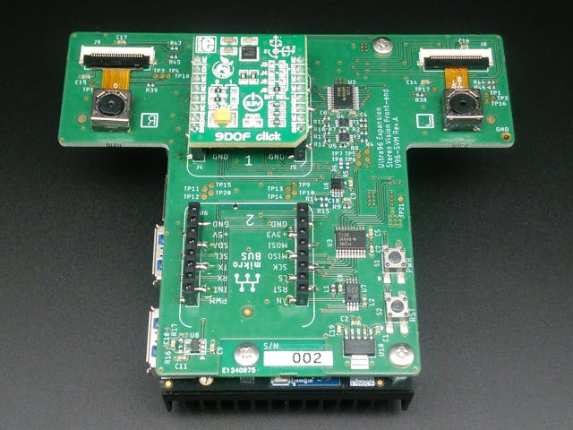
U96-SVM is an add-on board for Avnet Ultra96V2 with dual CMOS image sensors and two mikroBUS sites. This project contains a PCB design and a sample application operating on it.
All design files are shared at the following GitHub repository.
https://github.com/sdoira/U96-SVM
They are available under the following license.
- Hardware: TAPR Open Hardware License
- Software: MIT License
- docs --- some useful documents
- eagle --- hardware design files
- src --- git-controlled source files
- vitis --- Vitis working directory
- vivado --- Vivado working directory
The PCB is designed according to 96Boards Mezzanine Design Guidelines.
EAGLE 9.6.2 is used in designing the PCB. The number of layers is 4. The minimum trace width and minimum drill diameter are 0.15mm and 0.25mm respectively. This design rule is according to EuroCircuits 6D class.
This board has dual CMOS image sensors to retrieve stereo images and two mikroBUS sites for expansion.
OV5640 is chosen as an image sensor. The length between the two image sensors is 8cm. They are connected to Zynq SoC through the MIPI CSI interface. These signals are assigned to the High-speed expansion connector following 96Boards Camera Module Interface Addendum. No termination circuitry is necessary as the Zynq device has them inside. However, signal impedance and trace lengths for high-speed signal lanes should be designed carefully.
The designated differential impedance for differential signal lanes is 100-ohm. QucsStudio is used to calculate the impedance.
Trace lengths are matched using the EAGLE's meander tool.
Two mikroBUS sites are introduced to add some extensibility. They are connected to the Low-speed expansion connector following 96Boards specification.
Pin assignment of Low-speed and High-speed connectors are shown below. Signals from mikroBUS are connected to the same pin as Avnet 96Boards Click Mezzanine.
This project doesn't contain Gerber files. EAGLE board layout file (.brd) is directly used to order manufacturing.
If you want to place an order simply upload the BRD file to the EuroCircuits website.
/eagle/U96-SVM.brd
Their "PCB Visualizer" will show you the conceptional drawing of the PCB. Enter the number of PCBs and place an order.
The assembly service is also possible by enabling the "Include assembly" option then upload the BOM file.
/eagle/U96-SVM-BOM.xlsx
When you order assembly you may receive warnings of footprint mismatch. This happens because some components' footprints have origins different from their database. In this case, you just offset or rotate the components in the "PCB Assembly Visualizer" and tell them that their footprints are exactly matched.
You will also need to acquire the components for post-assembly such as OV5640 image sensors. Such components are described in the following document.
/eagle/BOM-Assy.xlsx
The top-level block design of the Vivado project is shown below.
Xilinx "MIPI CSI-2 Receiver" is used to receive image data. The format of image data is 8-bit YUV. These signals are fed to the user-created IP module "dvp" which DMA transfers the image data to DDR memory. The interrupt signal will be generated for the completion of the DMA transfer of each frame.
USB InterfaceThis device is recognized as USB Video Class (UVC) device when connected to the host PC. Such settings can be done by sending a chain of USB descriptors to the host PC during device enumeration. The USB descriptors used in this project are described in the following document.
/docs/USB_descriptor.xlsx
Wireshark was used during USB debugging. I captured USB descriptors sent from a USB web camera and used them as a starting point of my project.
Below shows a screenshot captured when U96-SVM is connected to the USB2.0 port.
Xilinx stand-alone USB driver "usbpsu" is used in this project. I extended this driver to adopt to UVC device class by adding class-specific request handlers. Currently, the following resolution is available for both USB2.0 and USB3.0 mode.
The left and right images are combined horizontally. The actual output image is twice wide.
USB product needs a unique pair of VID and PID. Openmoko assigned this project the following VID/PID pair. I express my appreciation for their support of this project.
This repository contains 2 Vivado projects. One of them is the Vivado top-level project. The other is a project for a user-created IP module. Both of them can be created by running TCL scripts. Refer to the following documents about how to create these projects.
/docs/create_project_dvp.pdf
/docs/create_project1.pdf
The Vitis project contains a sample application named "usb_grabber". This application, when launched, automatically starts DMA transferring of stereo images while waiting for a USB connection. Refer to the following document about how to create the Vitis project.
/docs/create_vitis_project.pdf
Launch the Vitis project to configure FPGA with the bitstream file and runs the "usb_grabber" application on Ultra96V2.
Connect J7 of Ultra96V2 with the USB port of the host PC. You need a USB cable with USB 3.0 A and Micro B connectors.
This device will show up on the Device Manager.
- Windows 10 Camera Application
Launch the "Camera" application.
Click the "switch camera" icon upper right corner of the screen.
Image outputs from the device will be displayed with the default resolution.
- OpenCV
Since this device is recognized as a generic USB video class device, OpenCV can open the device and receive the image data by simple code such as this.
void main (void)
{
    cv::VideoCapture cap(1);
    if(!cap.isOpened()) {
        return -1;
    }
    cv::Mat frame;
    while(1) {
        cap >> frame;
        cv::imshow("frame", frame);
        cv::waitKey(33);
    }
}Stereo images are successfully retrieved through MIPI CSI and transferred to the host PC through USB. The USB interface is configured as USB Video Class to eliminate the need of creating a device driver on the host side. Stereo vision applications can be created on PC and verified their performance before porting them to Zynq SoC.
Hardware is released under an open hardware license. Users can modify the hardware for different sensor configurations and manufacture on their own.


_t9PF3orMPd.png?auto=compress%2Cformat&w=40&h=40&fit=fillmax&bg=fff&dpr=2)


Comments
Please log in or sign up to comment.