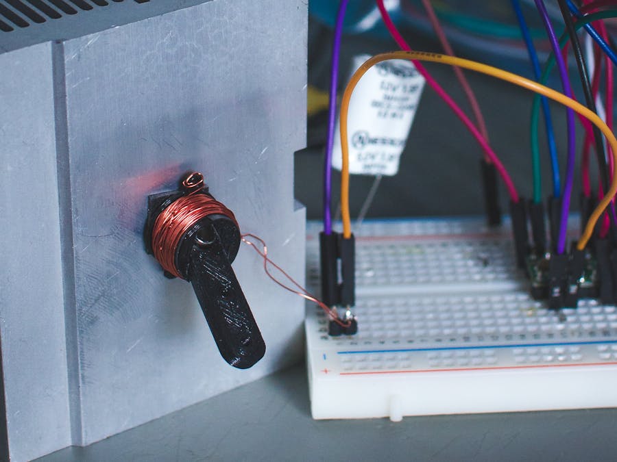
Upon research for an upcoming project, I discovered this simple way to make very tiny magnetic actuators. RC enthusiasts have been using these for some time now, but they don't seem very well known. I think there are a lot of useful applications for these little actuators, and they are simple enough to be designed by anyone, which means easy to implement in custom projects. Follow along in the video as I show you how to make the one designed and I will explain how it works. Although I have provided the files to 3D print my design, I encourage you to try and design your own!
Step 1: Watch the Video!P.s. If you enjoy my content, please consider subscribing to my YouTube Channel!
Step 2: Gather the Parts and ToolsParts:
- Magnet (I used this one for my design - McMasterCarr)
- Metal Rod - 1mm Diameter - I used the leads from a resistor.)
- Copper Core Wire, at least 30AWG - AdaFruit - or scavenge from old motor or electric clock.
- Electrical Tape
Tools:
- 3D Printer, or a service like Shapeways
- Soldering Iron(if you want to solder the leads on)
- Snips
- Tweezers(not essential)
- Patience (to wind the wire)
Download the parts from here! - https://www.thingiverse.com/thing:2859499
3D print the parts.
Step 4: Assemble the Body.Cut some pieces off of your metal rod(resistor in my case) and assemble the piece as shown in the GIF above. The small pieces of rod hold it together. You want the arm to be very loose, as these don't have a lot of power and any friction will really take away from it.
Step 5: Electrical TapeUse the electrical tape to cover the holes where you put in the metal rod, this makes sure they won't fall out.
Step 6: Start Coiling the WireAttach the wire to the frame and start coiling it around the circular part of it. Keep it going in one direction. The neater and tighter the coil, the better the magnetic field will be for the current that is supplied. Once fully wrapped, strip some of the enamel off of the wire and solder on some pin headers.
Step 7: Test It Out!I'm testing it by attaching it to a motor driver and microcontroller. This isn't a tutorial on how to do that so I won't go over it(I do cover some of the stuff in some other tutorials). Basically if you put a current though the wires(such as attaching a battery to each side. The coil will generate an electric field. The magnet will oppose that field in some way, and try to spin the actuator arm. This is what gives the movement. If you switch the polarity of the current(battery) it will make the actuator try and go in the other direction. Lots of explanation int he video. Very cool!
Step 8: Design Your Own!Since these are pretty simple in design, I encourage you to try and make a custom one for your own application. I would love to see what you come up with!
Step 9: Support These Projects!If you haven't noticed yet, my goal is to bring fun, interesting, educational projects that are available to everyone equally with zero pay walls. However, these projects do cost me both time and money in developing them. If you enjoy these free open source projects, and can spare a few dollars a month, please consider joining my Patreon. Patrons help support future projects, so I can continue to bring more content to everyone!
If you want to keep up to date on my projects, subscribe to my YouTube! Watching and sharing my videos is another way to support what I do.
And finally, follow me on Twitter and Instagram, where you will find behind the scenes content for future projects. Its also an easy way to ask me questions.


Comments