


Water Flow Sensor, as the name suggests, is a device to measure the flow of water.Accurate flow measurement is an essential step both in the terms of qualitative and economic points of view. Flow meters have proven excellent devices for measuring water flow, and now it is very easy to build a water management system using the renowned water flow sensor YF-S201. This sensor sits in line with the waterline and contains a pinwheel sensor to measure how much water has moved through it. There is an integrated magnetic Hall-Effect sensor that outputs an electrical pulse with every revolution.
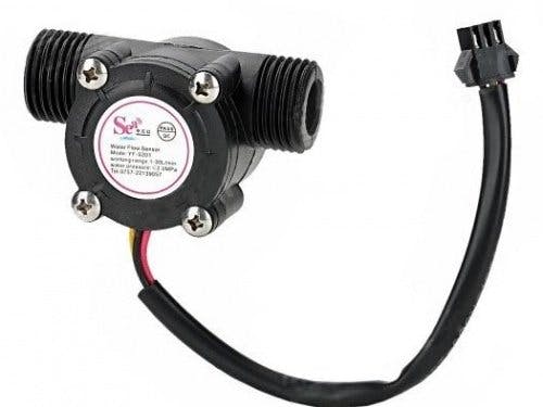
Working of the Water SensorThe sensor has 3 wires RED, YELLOW, and BLACK as shown in the figure below. The red wire is used for supply voltage which ranges from 5V to 18V and the black wire is connected to GND. The yellow wire is used for output (pulses), which can be read by an MCU. The water flow sensor consists of a pinwheel sensor that measures the quantity of liquid that has passed through it.
Basically, the YF-S201 Water Flow Sensor consists of a Flap Wheel (or a Turbine Wheel) that spins when water flows through the sensor. At the center of this flap wheel, there is a magnet fixed. Keeping this in mind, when the water flows through the YF-S201 Water Flow Sensor, the flap wheel spins due to the force of the water and as a result, the magnet attached to it will also spin. As a result, the magnetic field near the Hall-effect sensor switches polarity as the flap wheel spins, and the output of the sensor (on the output Pin – Yellow Wire) will be a pulse.
By keeping track of the number of pulses from the output of the Water Flow Sensor, you can easily calculate the amount of water flowing through the sensor and as a result the Water Flow Rate.
Connections· Connect the Red and Black wires of the YF-S201 Water Flow Sensor to +5V and GND.
· Since will be used the Interrupt feature of the Arduino, only Digital I/O Pins 2 and 3 are possible to connect to the Output of the Water Flow Sensor.
In this project, the Output of the Water Flow Sensor (Yellow Wire) is connected to Digital I/O Pin 2 of Arduino UNO.
CodeThe code for the Arduino Water Flow Sensor Interface is given below.
const int watermeterPin = 2;
volatile int pulse_frequency;
unsigned int literperhour;
unsigned long currentTime, loopTime;
byte sensorInterrupt = 0;
void setup()
{
pinMode(watermeterPin, INPUT);
Serial.begin(9600);
attachInterrupt(sensorInterrupt, getFlow, FALLING);
currentTime = millis();
loopTime = currentTime;
}
void loop ()
{
currentTime = millis();
if(currentTime >= (loopTime + 1000))
{
loopTime = currentTime;
literperhour = (pulse_frequency * 60 / 7.5);
pulse_frequency = 0;
Serial.print(literperhour, DEC);
Serial.println(" Liter/hour");
}
}
void getFlow ()
{
pulse_frequency++;
}
The output of the project is to display the quantity of water flowing through the sensor in liters per hour as shown below.
Since the output of the sensor is a pulse, by calculating the frequency of the pulse, we can calculate the volume of the water flowing through the sensor.
The pulse frequency in Hz is 7.5 * Flow Rate (in Litres per minute). So, the quantity of water in Litres per Hour is Pulse Frequency * 60 / 7.5.
Thus now you can calculate the rate of flow of water with the help of this water sensor. See More of Water sensors and try building your water sensing unit.
This guide was written in reference to the tutorial published by electronicshub.com.


Comments
Please log in or sign up to comment.