


Hardware components | ||||||
 |
| × | 2 | |||
| × | 1 | ||||
Software apps and online services | ||||||
 |
| |||||
| ||||||
You have a microcontroller and two identical sensors, meaning that they have the same I2C address. Without a multiplexer or the possibility to configure the I2C address of the sensor you cannot attach them to the same I2C bus. However, on a board that provides the ability to configure any GPIO pin pairs as an I2C bus, you can connect the two sensors to their own individual I2C buses.
The IngredientsIn this example we use an ESP32, which supports multiple I2C buses and two Sensirion SCD41 CO2 sensor evaluation boards. You can use any two sensors, whether they are the same product or different sensors with the same I2C address. The evaluation boards are convenient, as we can connect them with the cables included in the Evaluation Kit.
General working principleThe two SCD41 sensors we want to connect have an I2C address of 0x62, which cannot be changed. Therefore, to communicate with both sensors from the microcontroller, we will use a separate I2C bus for each. Each I2C bus requires one pin for the SDA line and one for the SCL line. The first sensor will be attached to the standard I2C pins. For the second I2C bus, we need to define two GPIO pins to use and connect the second sensor to those pins. On the software side we use the standard Wire library. You can use the pre-configured "Wire" instance from for the first sensor connected to the default pins. For the second sensor, we will need to configure a second instance, "Wire1", to use the chosen pins. As a final step, we will create two instances of our sensor driver class and initialize one with the standard I2C bus and the other with the custom I2C bus.
WiringFirst, we need to define the pins we will use for the two I2C buses. For I2C bus A, we can use the default I2C pins of the board. For the ESP32 DevKitC, these are pin 21 (SCL) and pin 22 (SDA). For I2C bus B, we can choose any two GPIO (General Purpose Input Output) pins. If you are using a different board, it is important to check the specifications to determine if any pins have special configurations that prevent them from being used as GPIO pins. In our case, we have selected pins 17 and 16 for I2C bus B.
Pull-up resistors
Having pull-up resistors in place on the I2C data (SDA) and clock (SCL) lines is important for a good signal quality and robust communication. You can read more about it on I2C Pull-Up Resistors Intro.
The ESP32 DevKitC Board ensures that GPIO lines are automatically pulled to a high state. Therefore, there is no need to manually wire or configure pull-up resistors for the pins you intend to use.
Wiring diagram
Since the SCD41 sensor is compatible with both 3.3V and 5V, we can connect one sensor to the 3.3V pin and the other to the 5V pin. If both sensors require the same voltage, they can be connected through a breadboard.
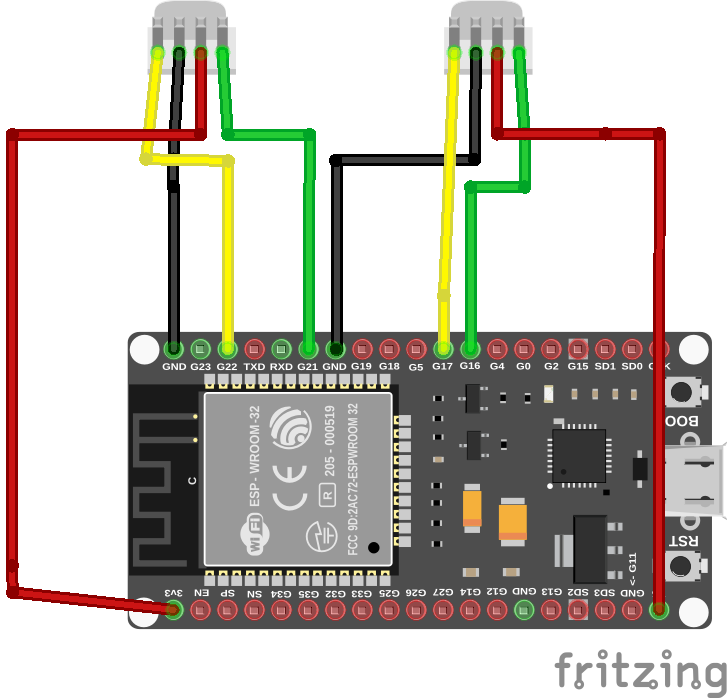
For this example, the wiring should be carried out as you see in the following diagram:
- SEK-SCD41 A - Pin 1 to ESP32 Pin 22 (SCL, yellow cable)
- SEK-SCD41 A - Pin 2 to ESP32 GND (Ground, black cable)
- SEK-SCD41 A - Pin 3 to ESP32 3V3 (Sensor supply voltage, red cable)
- SEK-SCD41 A - Pin 4 to ESP32 Pin 21 (SDA, green cable)
- SEK-SCD41 B - Pin 1 to ESP32 Pin 17 (SCL, yellow cable)
- SEK-SCD41 B - Pin 2 to ESP32 GND (Ground, black cable)
- SEK-SCD41 B - Pin 3 to ESP32 5V (Sensor supply voltage, red cable)
- SEK-SCD41 B - Pin 4 to ESP32 Pin 16 (SDA, green cable)
When configuring the software later on, it is important to remember the pins allocated for the second I2C bus. Specifically, we used pin 16 for the I2C data (SDA) and pin 17 for the I2C clock (SCL) and.
Software setupFirst, you need to include the Wire library:
#include <Wire.h>We are using the Arduino ESP32 platform, which includes the Wire library.
We can use the Wire instance without any modification for the sensor attached to the "I2C bus A" (default I2C bus). We just need to initialize the bus with:
Wire.begin();For the "I2C bus B" we need to configure a custom TwoWire instance. There is a predefined instance named Wire1 we can configure to use the pins we defined with the following lines of code within the setup() function:
const int sda_B = 16;
const int scl_B = 17;
Wire1.begin(sda_B, scl_B);
Then, the code sending the commands to the sensors over the I2C bus needs to know which bus to use for which sensor. Thus, you need to configure the sensor instances accordingly. First, create a driver instance per sensor.
Their scope should be global, such that those can be referred to from within setup() and loop().
SensirionI2cScd4x sensorA;
SensirionI2cScd4x sensorB;
Then, in the setup() function, assign the I2C buses to the sensors:
sensorA.begin(Wire, SCD41_I2C_ADDR_62);
sensorB.begin(Wire1, SCD41_I2C_ADDR_62);
Make sure that you really have Wire1 assigned for sensorB, so that it uses the custom set-up I2C bus.
You can now send any I2C command to the sensor, such as initiating the measurement and retrieving values.
sensorA.startMeasurement();
sensorB.startMeasurement();
...
You can find more details and options how to configure several I2C buses on the ESP32 platform using the Arduino IDE under ESP32 I2C Tutorial
Example sketch
You find a complete example sketch for ESP32 on GitHub arduino-i2c-different-buses-example.


Comments
Please log in or sign up to comment.